
Welcome to my world of Sn3 Scale Model Railroading

Trestles Of The C&TT RR
By
Tom Troughton, MMR
My C&TT RR was started in 1995 and designed to have plenty of mines, trestles and narrow, cliff hugging right-of-ways in much the same vein as the C&TS and Durango & Silverton railroads. |
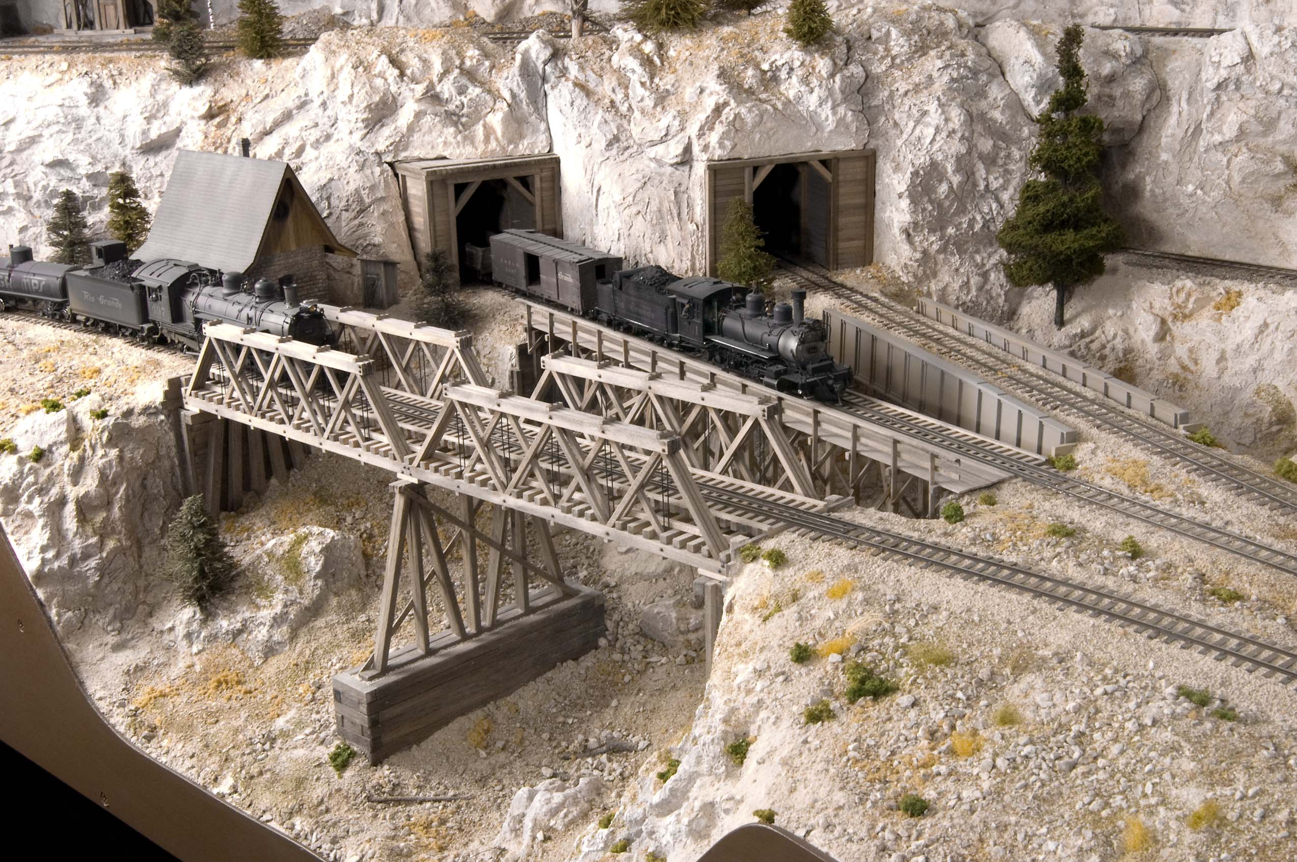 Photo 1 This aerial view shows the three bridges at Silver King Junction. The trio is composed of a pair of truss bridges, a timber trestle with walkway and a plate girder bridge. | 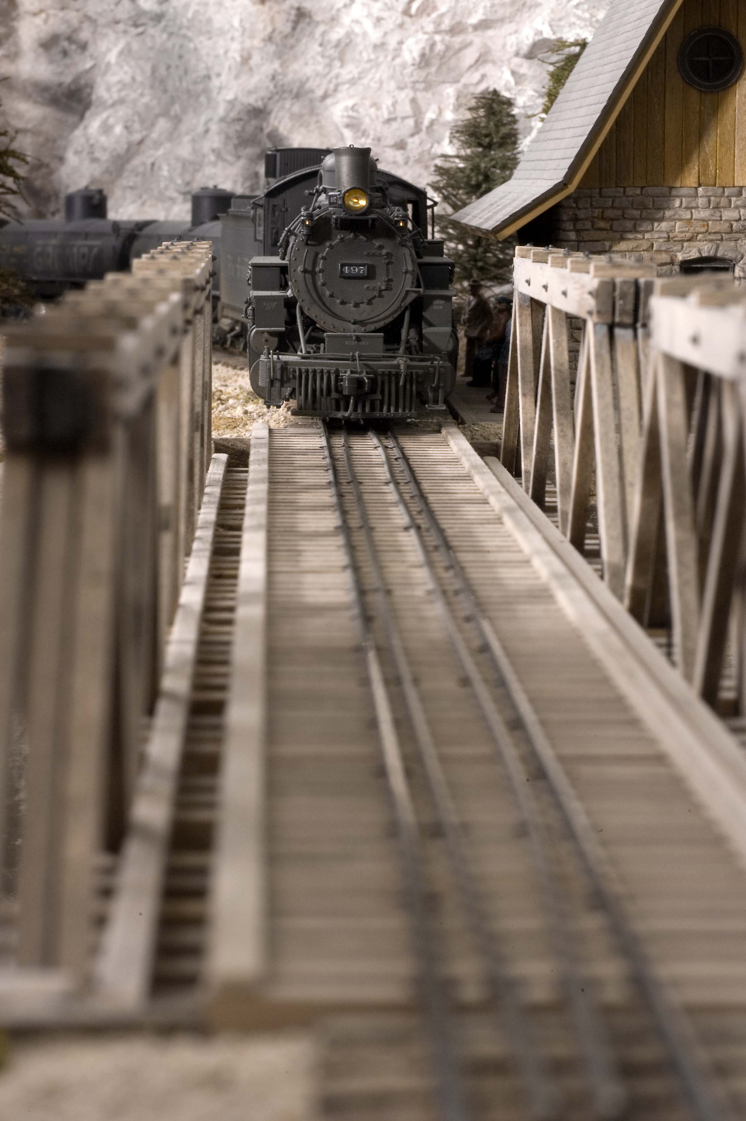 Photo 2 This head-on view shows D&RGW #497 at the approach of the twin truss bridge at the junction. The trusses and their center timber bents were drawn using Cadrail and scratch built by gluing pieces of strip wood directly to print outs of the drawings. |
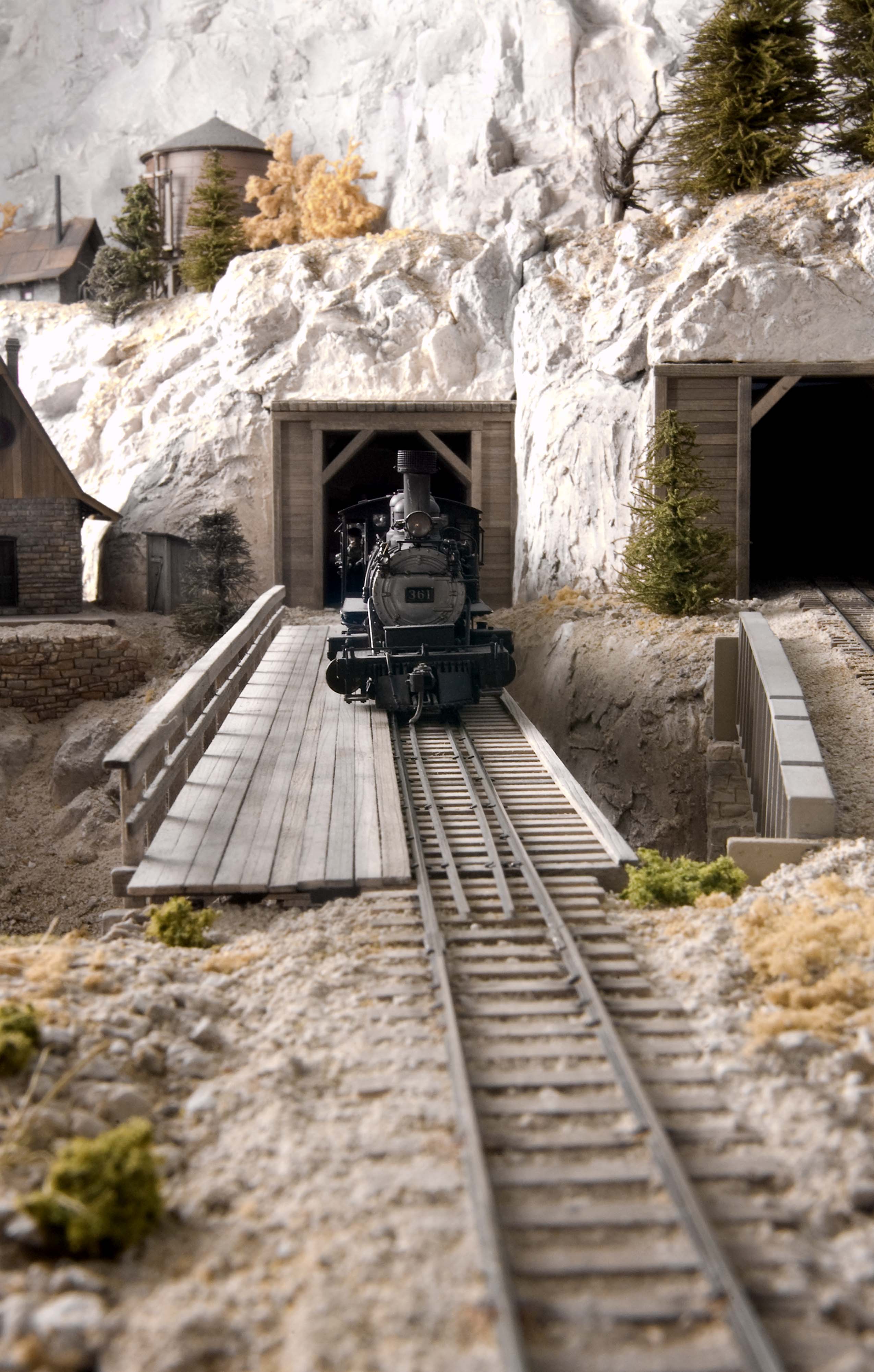 Photo 3 This head-on view shows D&RGW #361 on the timber bent trestle as it exits one of the tunnels at Silver King Junction. The extra wide planked walkway allows railway workers a safe crossing when thay have to cross the trestle when working on the line. The walkway is supported on extra long ties with angle braces supporting the railing posts from below. | 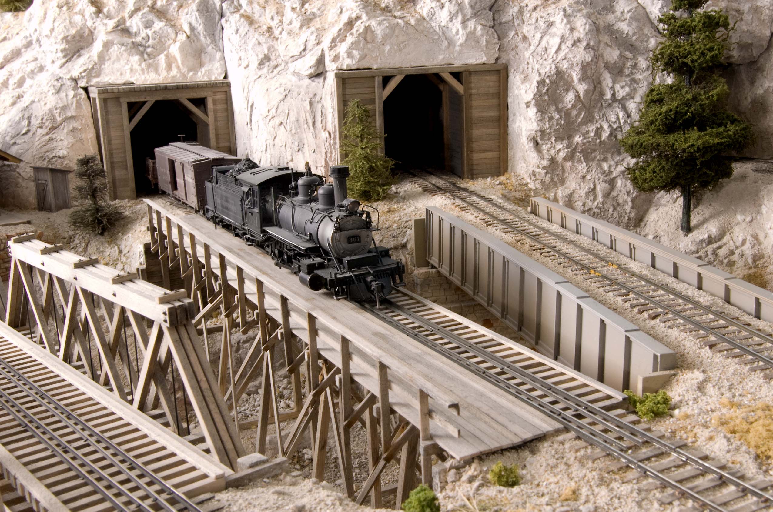 Photo 4 Engine 361 is easing onto the timber bent trestle at Silver King Junction on track leading from a hidden storage yard. |
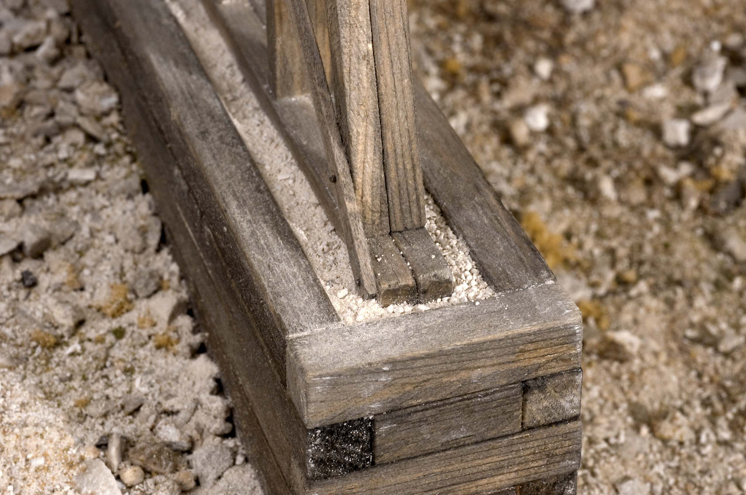 Photo 5 The center abutment for the twin truss spans at Silver King Junction is made up of large timbers. There's a centering, "key", hidden below the center bents that helps align the bridge when it's returned to the layout. The space around the base of the bents is filled with crushed limestone ballast. | 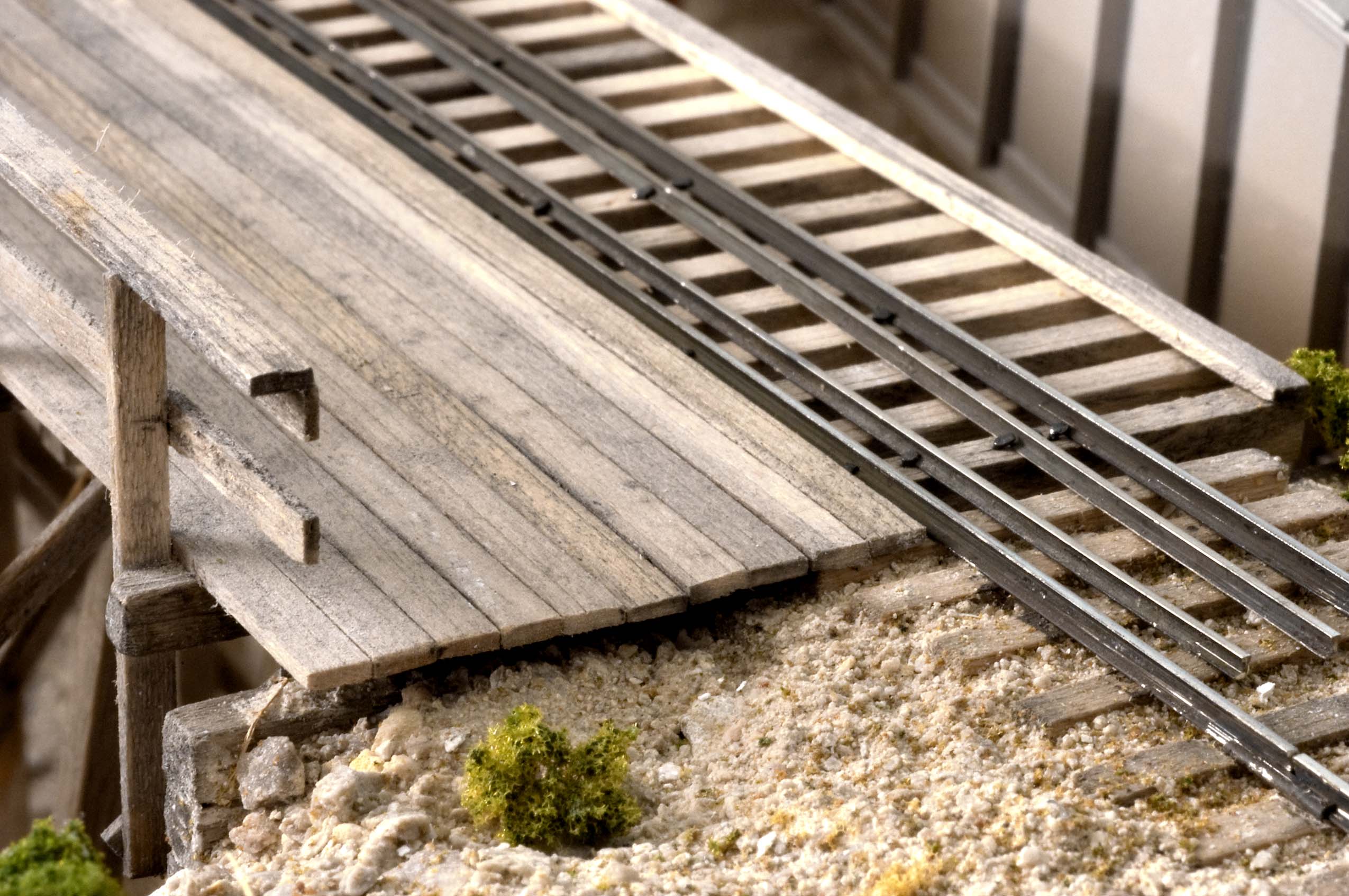 Photo 6 Here's a closer view of the walkway planks on the timber bent trestle at Silver King Jct. The random length boards were glued to the extra-long ties. Angle braces below the walkway support the wooden railing. | 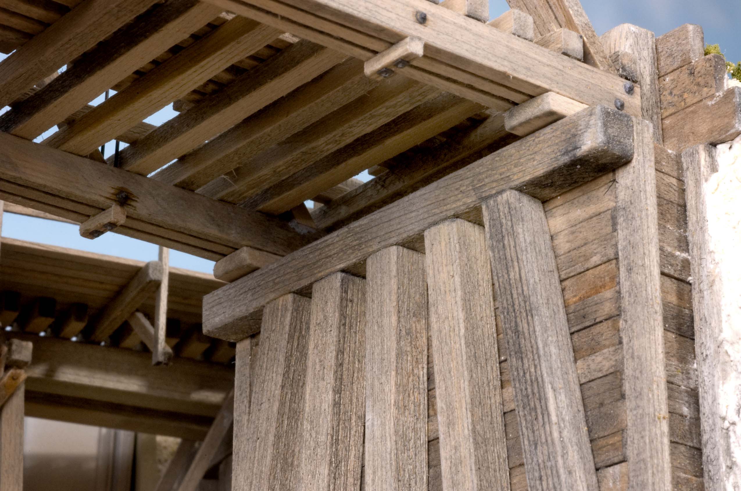 Photo 7 This underside view of the truss bridges at Silver King Jct. show the heavy supporting timbers and the wooden abutments. Also note the short strips of wood at the vertical truss rod locations. | 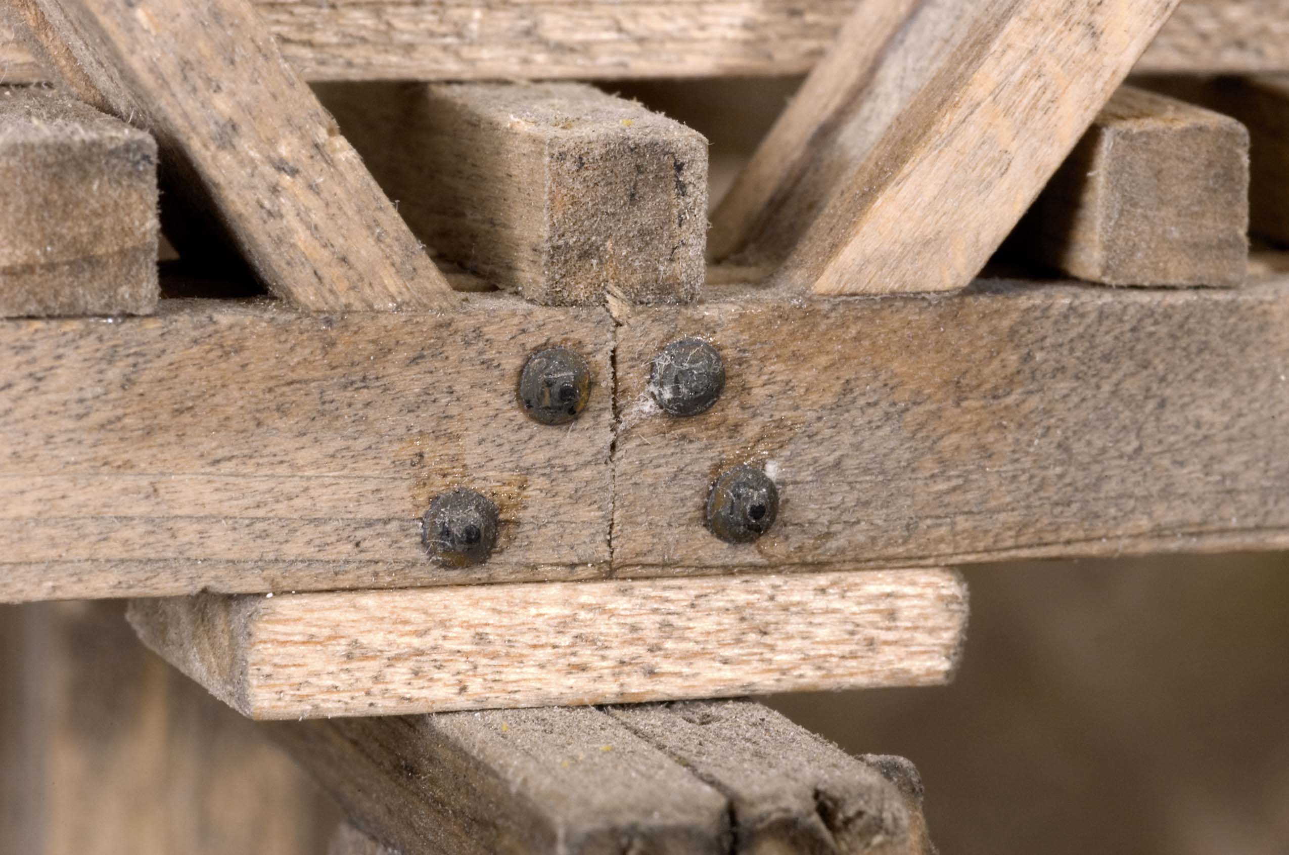 Photo 8 This close up view shows the Grandt Line NBW castings and a timber plank serving as a,"shoe," to support the junction of the 8" x 24" timber beams where they rest atop the center bents of the twin truss bridge. |
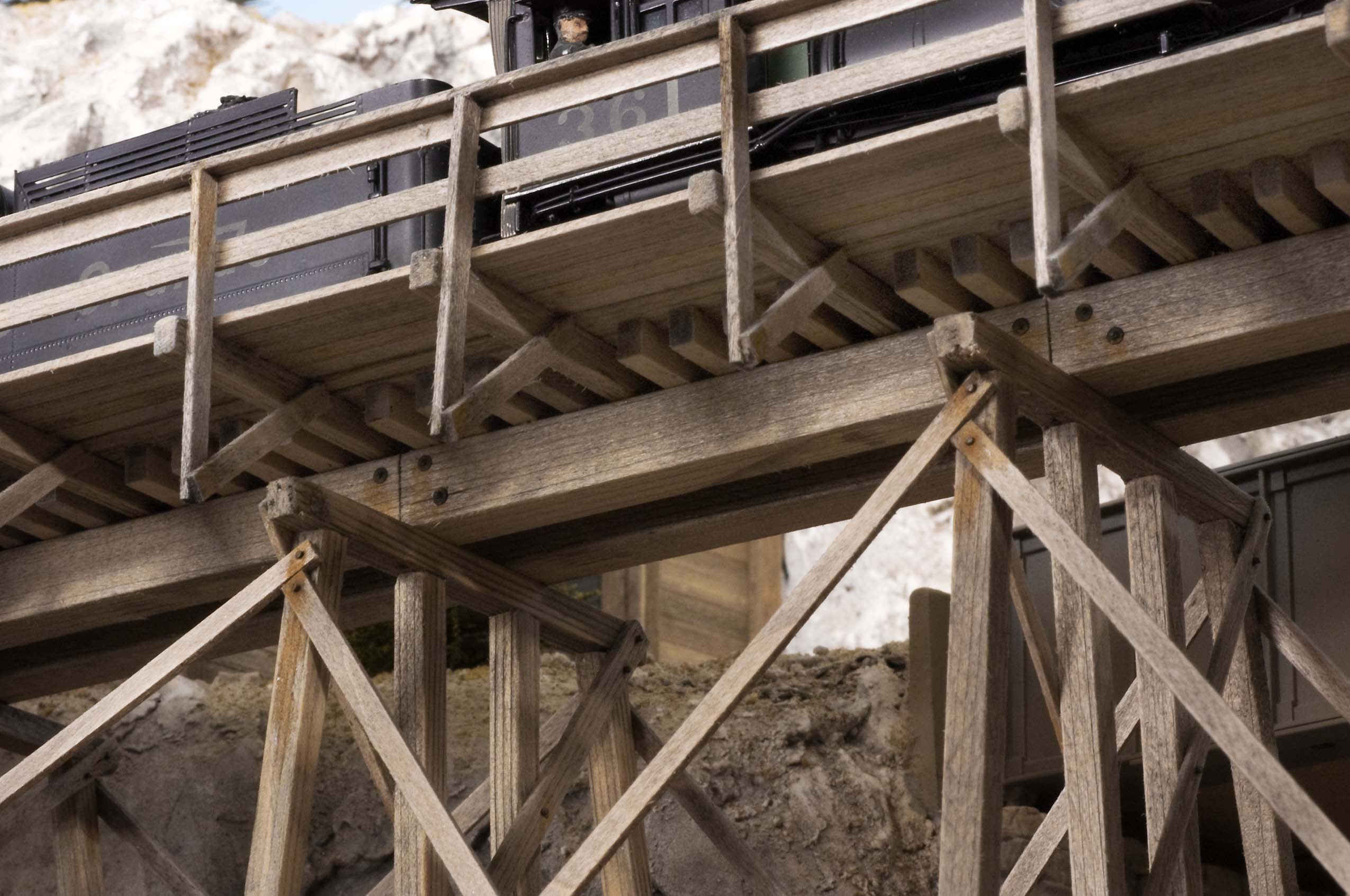 Photo 9 What looks like separate timbers as the main beams are actually cuts from an X-acto knife. Both of the beams are single pieces of scale 24" square strip wood. The diagonal braces for the railing and the braces between the bents are clearly visible too. The vinegar and steel wool rusting solution was liberally applied around every location where NBW castings and the small brads were used. | 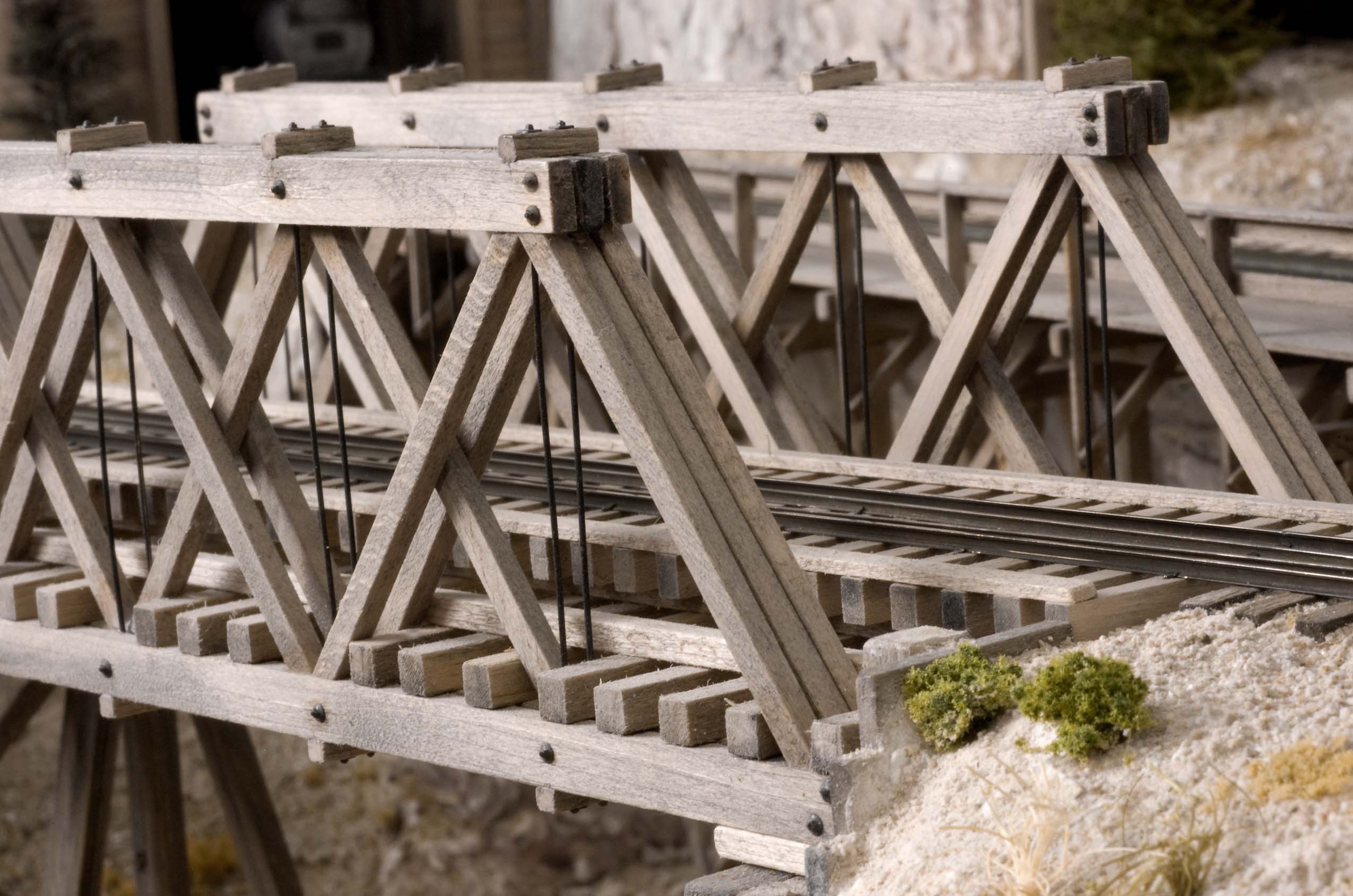 Photo 10 The truss rod pairs are clearly visible along with the short timbers at their end NBW castings. It's also easier to see the three sets of trusses used in each side component. A lot of strip wood was used in the construction of this twin span truss bridge. |
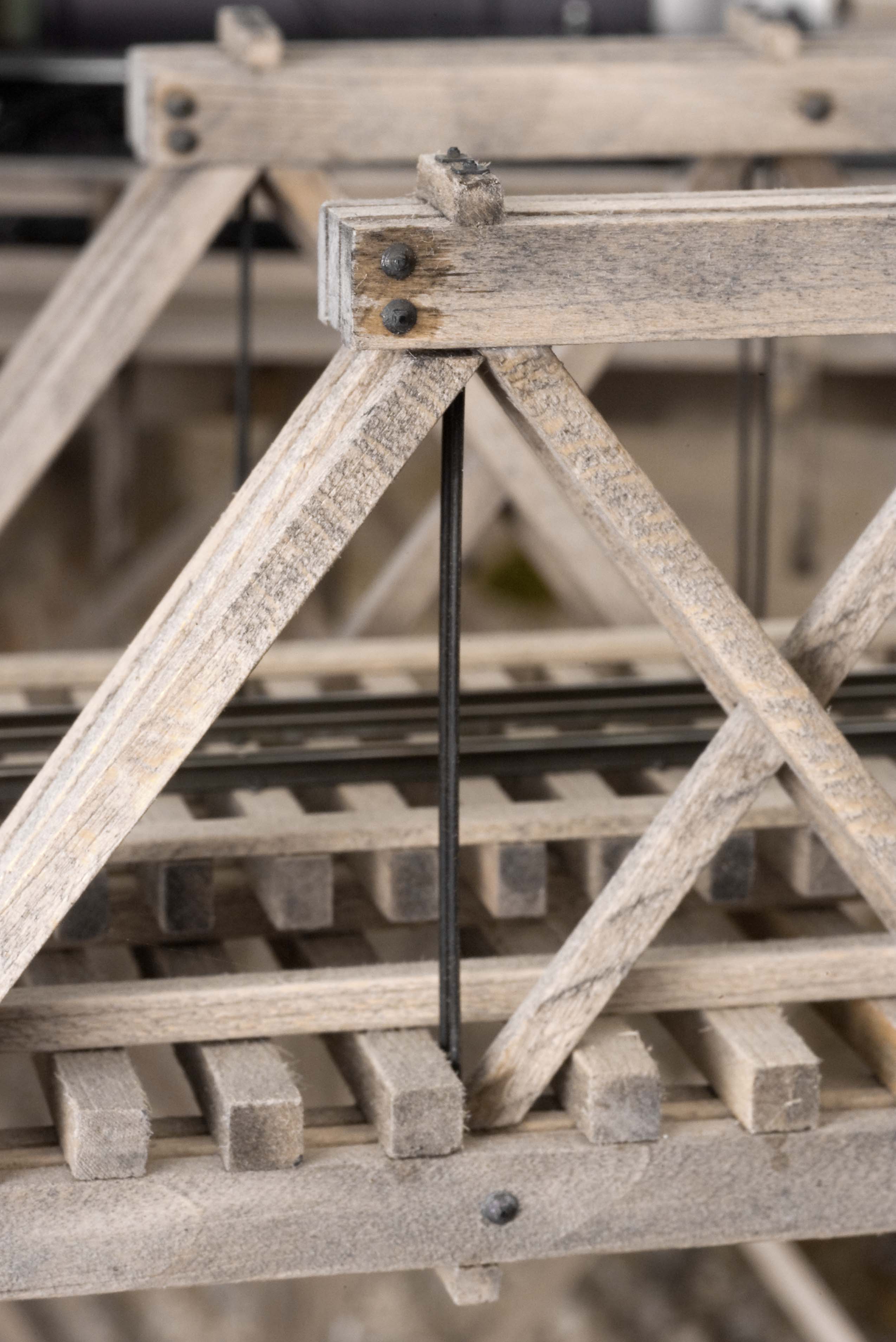 Photo 11 This view shows a pair of the truss rods used in the construction of the twin truss bridges. Music wire was cut to length, chemically blackened with printed circuit etching and gun bluing solutions then inserted through square blocks of wood above and below the main bridge chords. The NBW castings, representing their ends, were made from, "5-Minute" epoxy. | 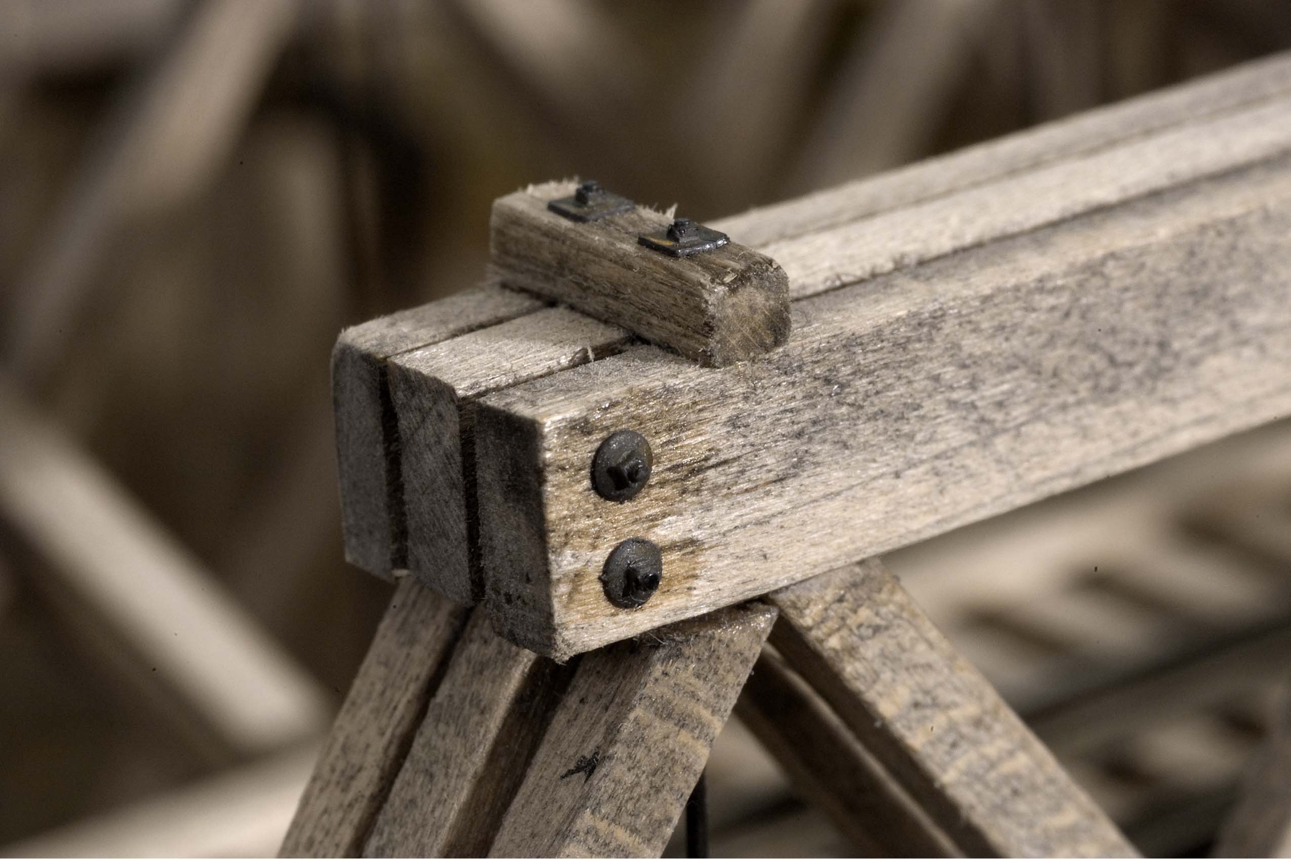 Photo 12 Grandt Line NBW details were used to represent the connecting bolts holding the three upper chords together on the twin span truss trestles. Secured in place with CA adhesive, they were given additional weathering with a rusting solution. |
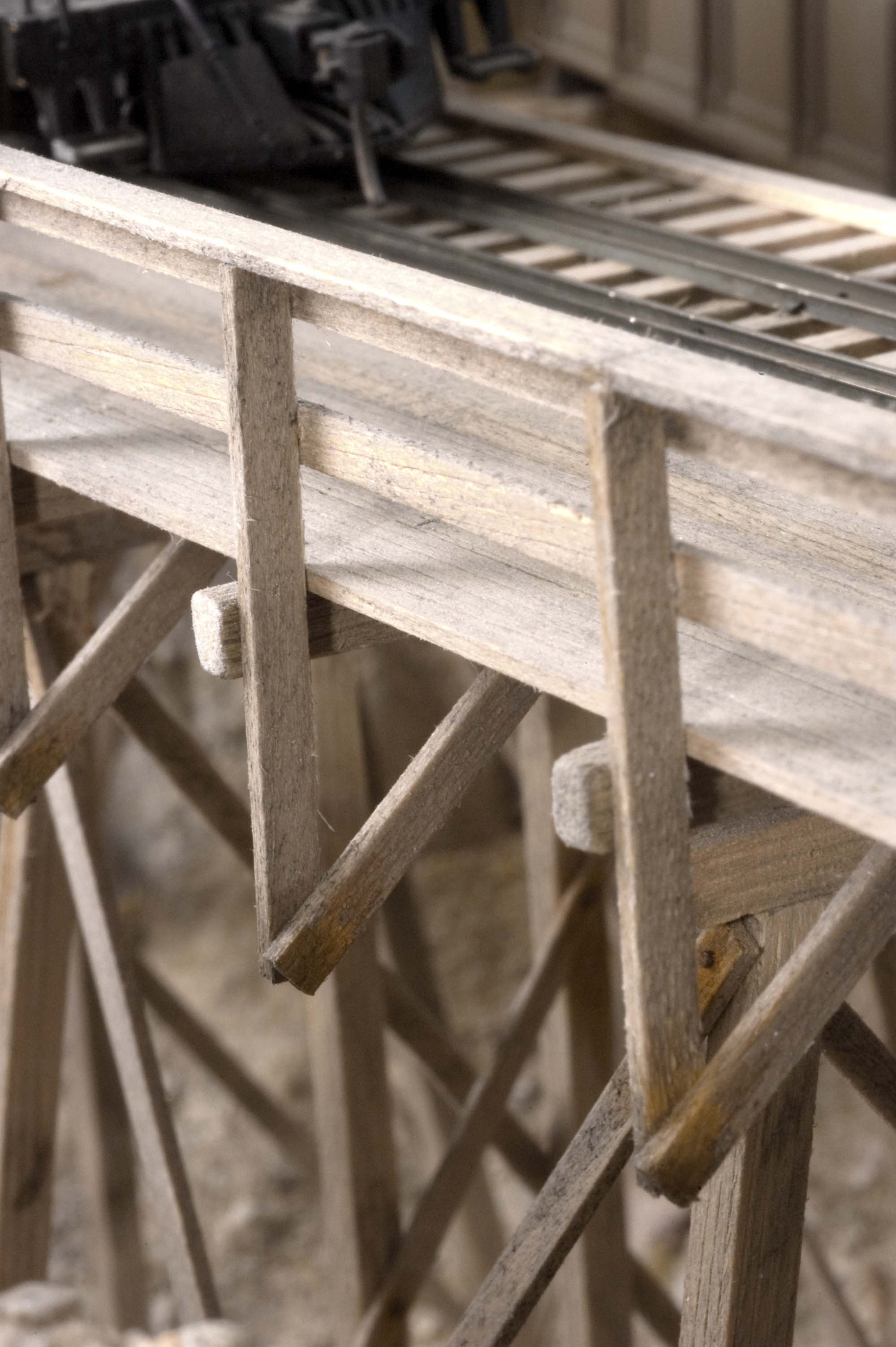 Photo 13 The protective handrail is supported by posts and angled braces that extend downward from the extended ties. | 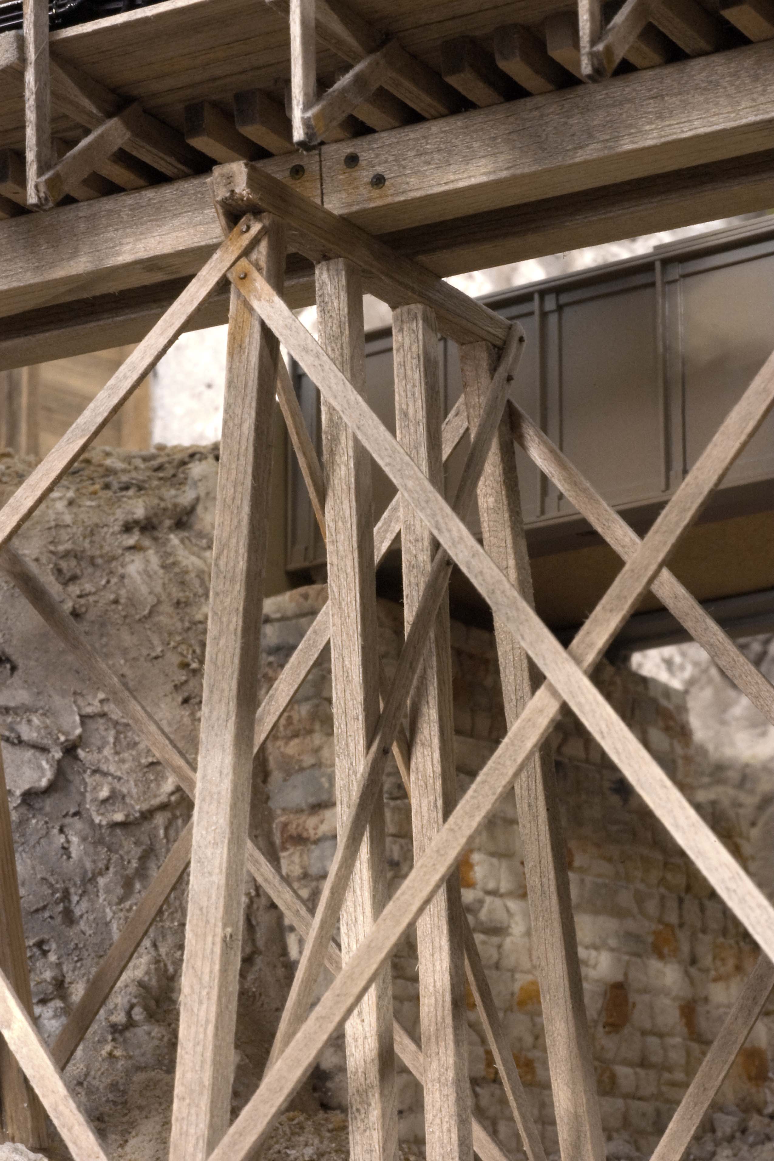 Photo 14 This underside view shows one of the bents for the timber trestle. The individual bents are strengthened by the use of diagonal braces while additional diagonal timbers connect all the bents together to reinforce the entire structure. |
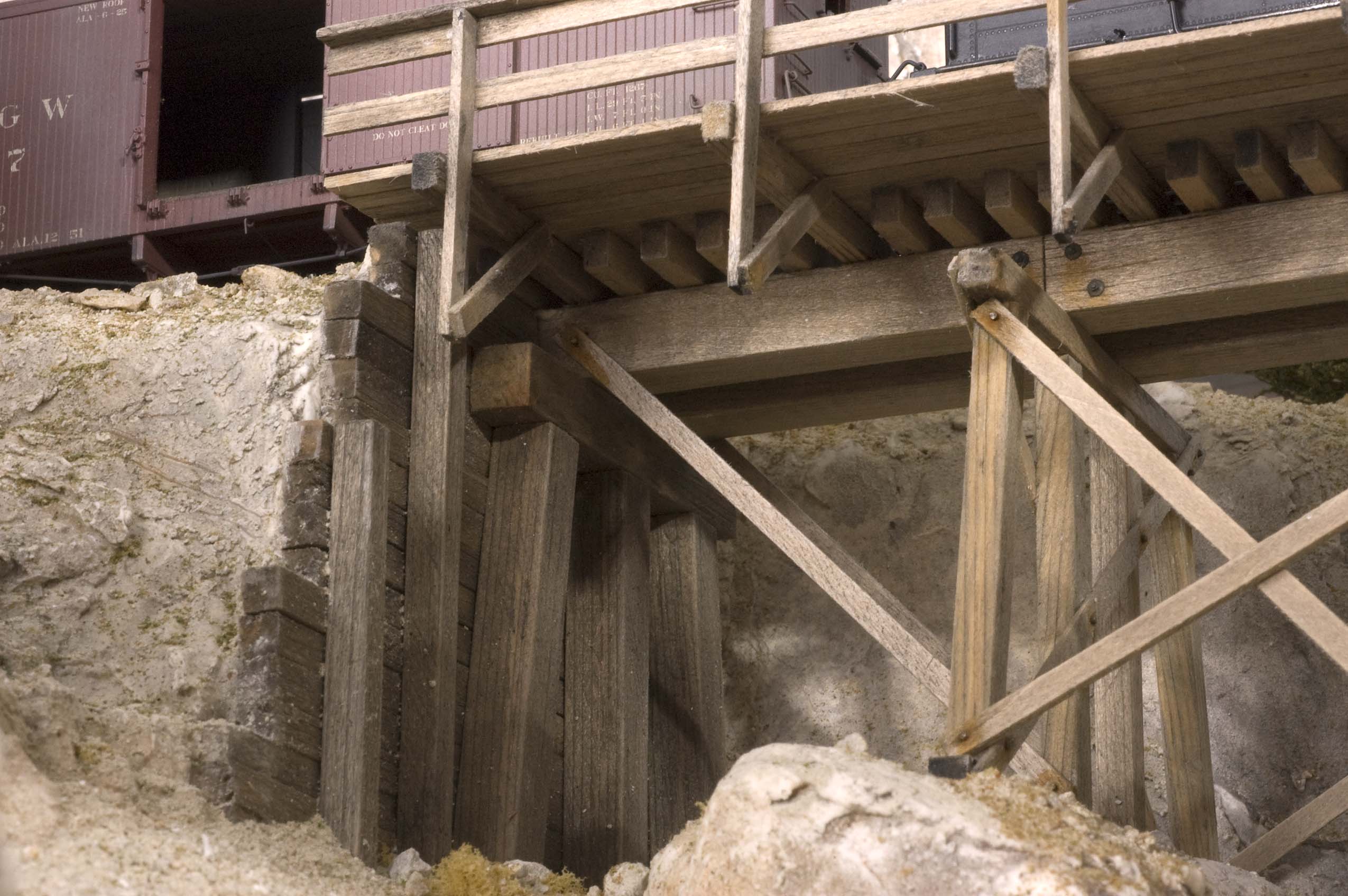 Photo 15 Here's another view of the underside of the timber bent trestle showing the large timbers used in its construction. | 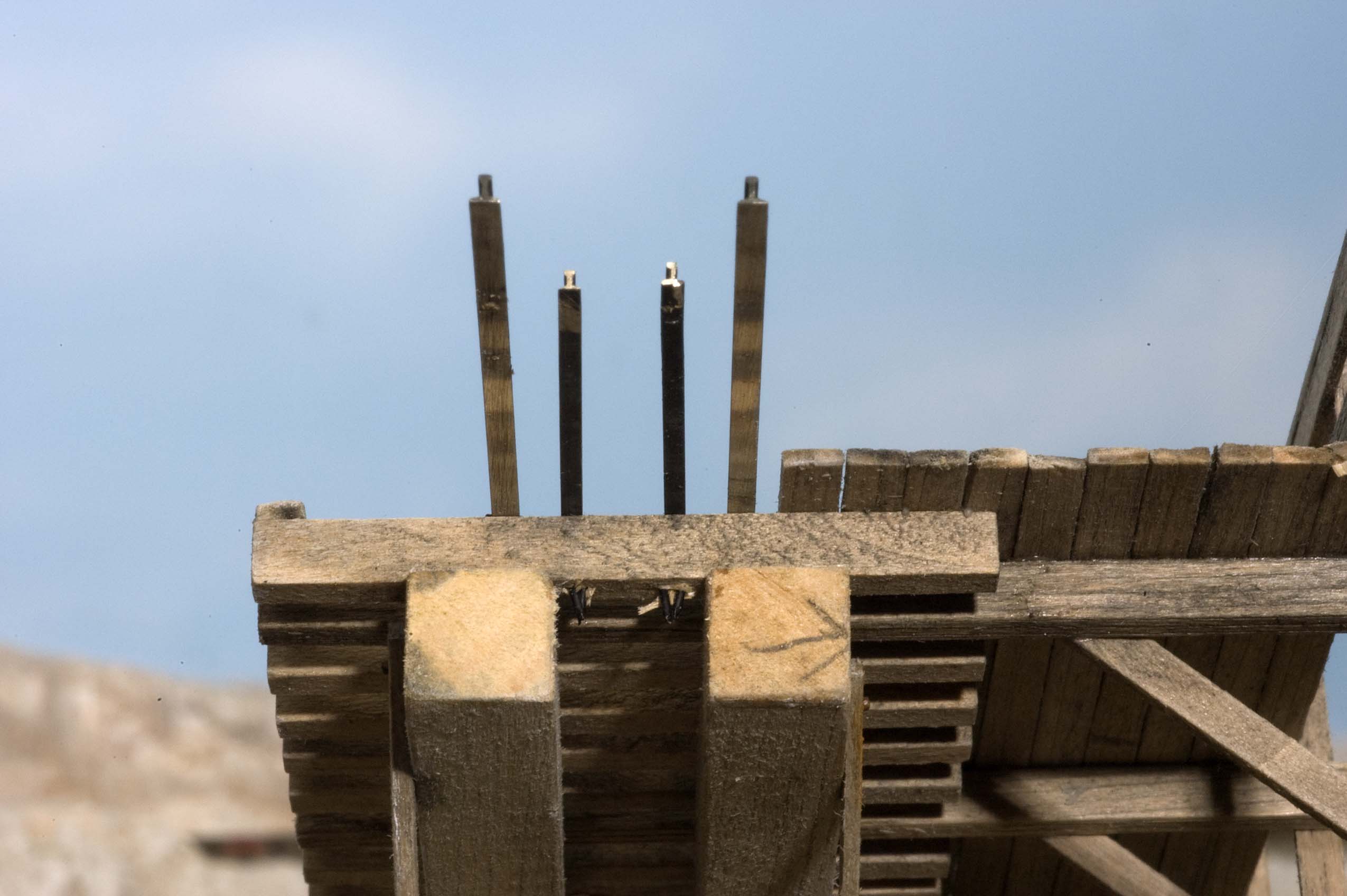 Photo 16 The rails of most of the trestles on the layout extend about 2" beyond their ends. That short amount of track is enough to support the trestle when it's being inserted into the keyways build into the abutments, plus it helps provide a smooth transition from the roadbed to the trestle. |
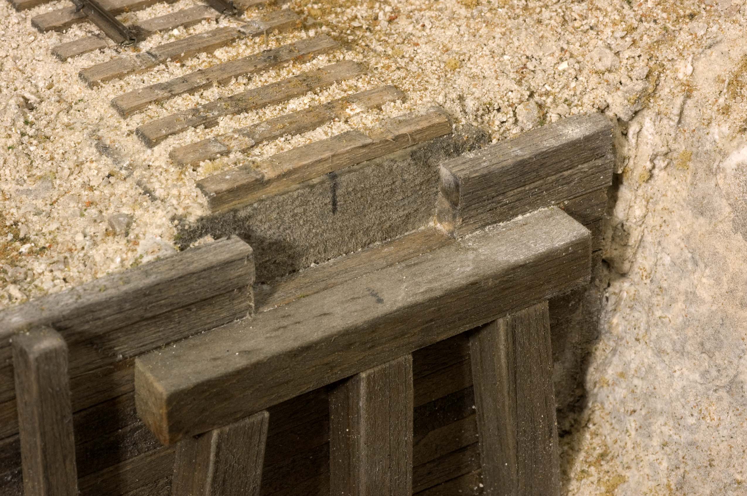 Photo 17 This is a view of one of the keyways built into the abutments. They're designed to be invisible after the large timber stringers are slid into place in the notch. The notch also assures realignment when the trestle is reinstalled on the layout. | 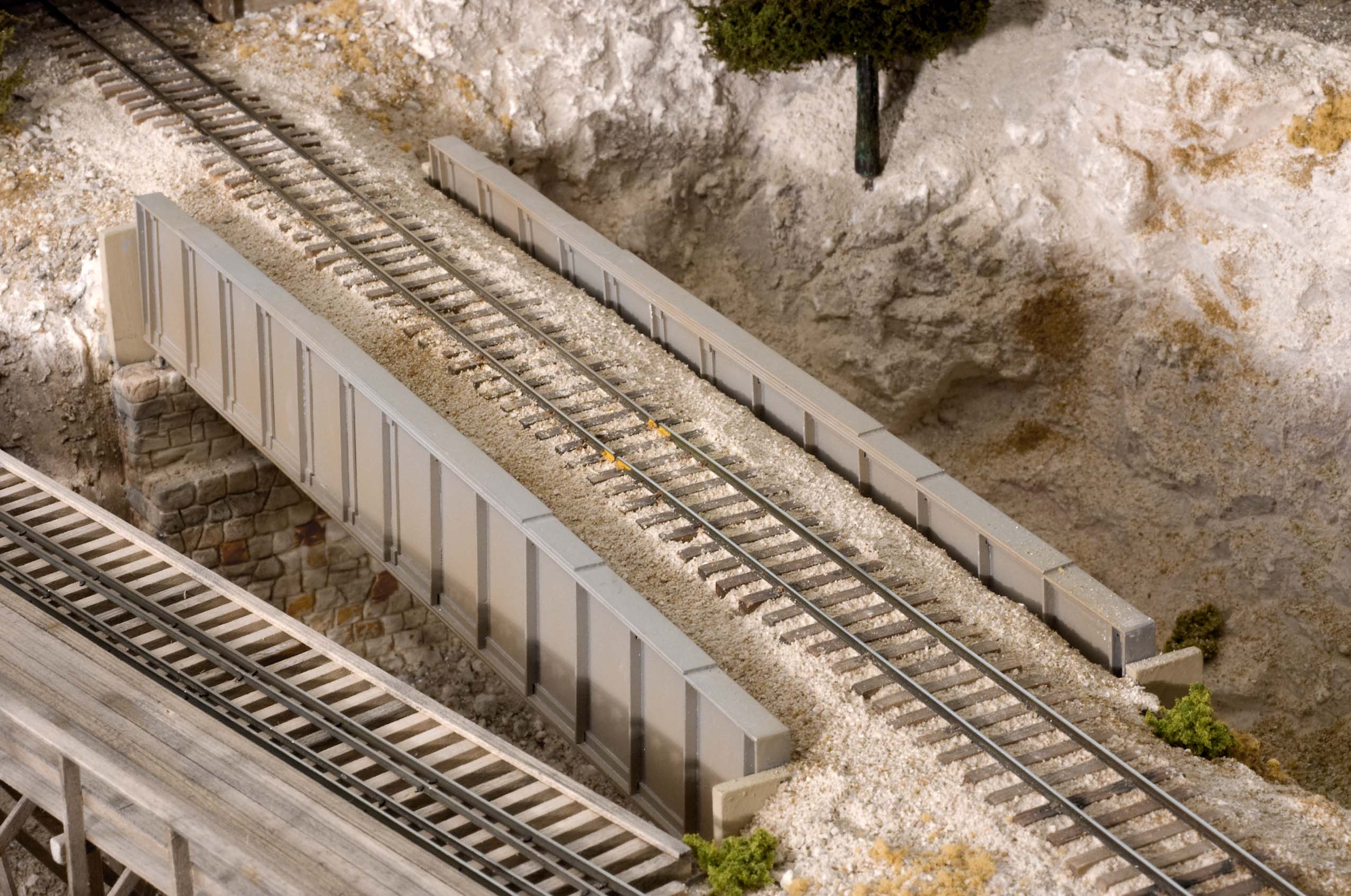 Photo 18 While not a wooden trestle, this photo shows the steel girder bridge at Silver King Jct. It was made of styrene and is held in place by carefully sliding it between the sub-roadbed and the stone abutments. |
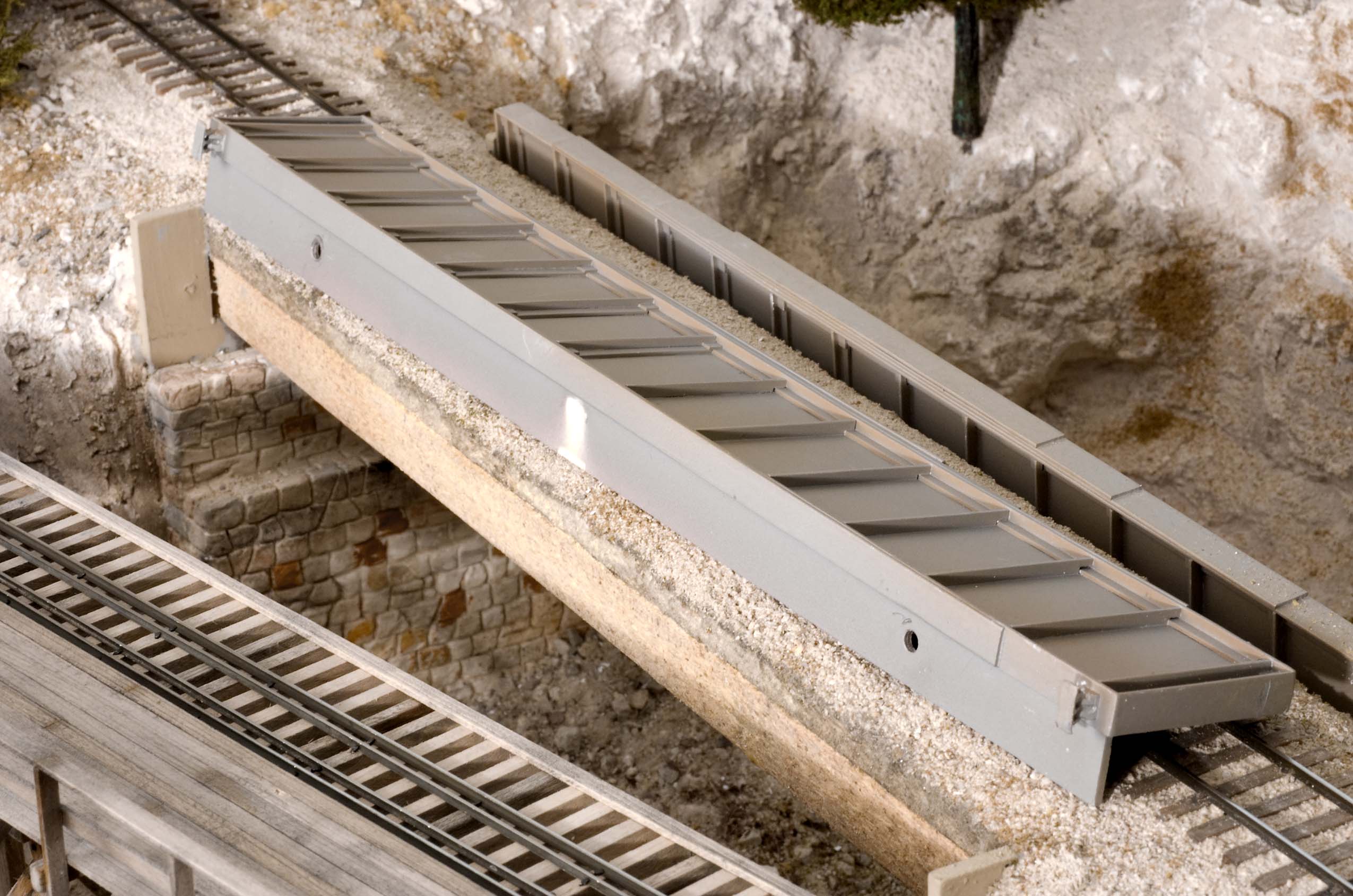 Photo 19 The girder bridge has a short flange of styrene attached to each of its side pieces to help hold them in place when they're wedged under the wooden sub-roadbed and the stone looking abutments. | 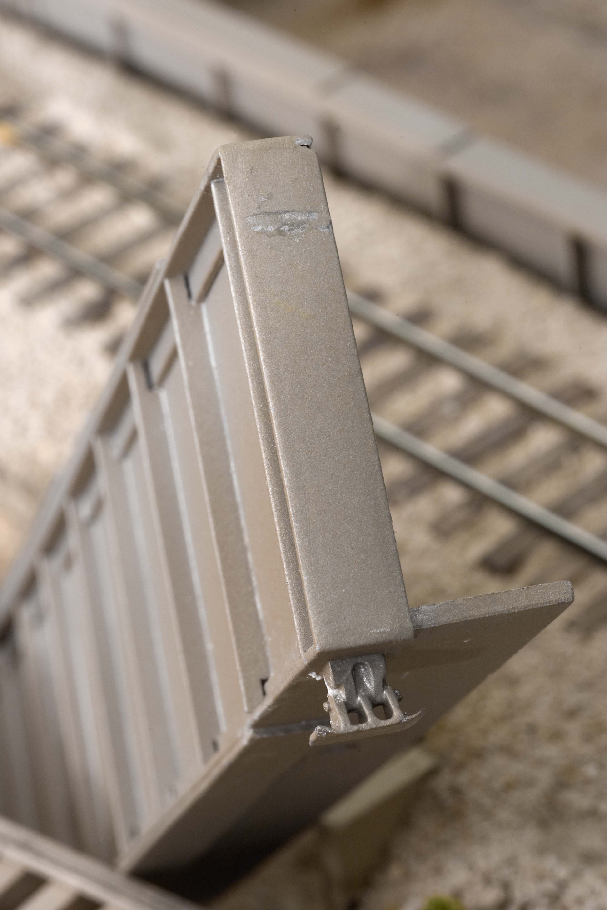 Photo 20 This end view of one of the side panels shows the metal bridge shoe and the vertical side ribs. The short horizontal piece extending to the right helps hold it in place when it's set in position between the bottom of the sub-roadbed and the stone abutment. |
 Photo 21 One of the first scenes visitors see when entering the train room is a short, curved trestle at the community of Tall Timbers. It's a simple open deck, timber bent trestle spanning a small ravine. | 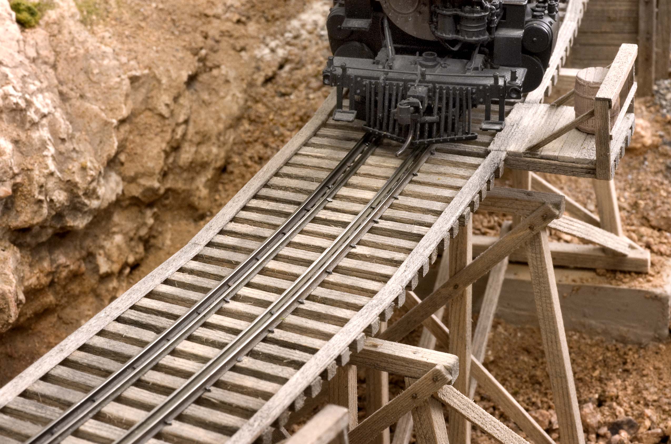 Photo 22 The trestle at Tall Timbers has a set of inner guard rails made from code 55 rail. A HOn3 track gauge was used to space the rails because I still had a few pieces of HOn3 equipment and wanted to be able to set it in place for photos. |
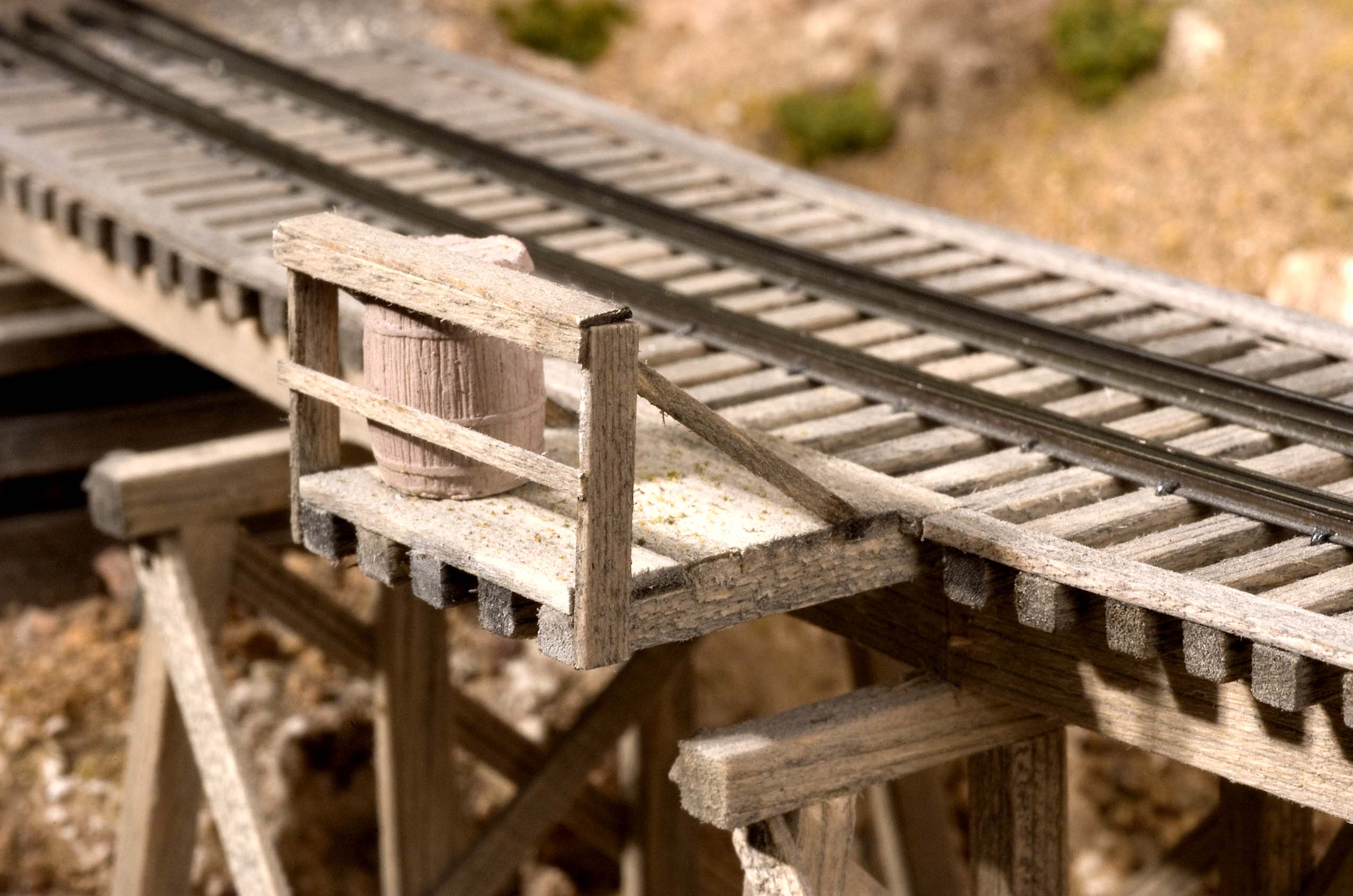 Photo 23 As on the other trestles, 15' long ties were used to support fire barrel locations. Unlike the others however, the diagonal braces that support the guard railing are located above the platform instead of below it and had to be positioned so they wouldn't be struck by the rotary snow plows or engines with large wedge shaped plows. | 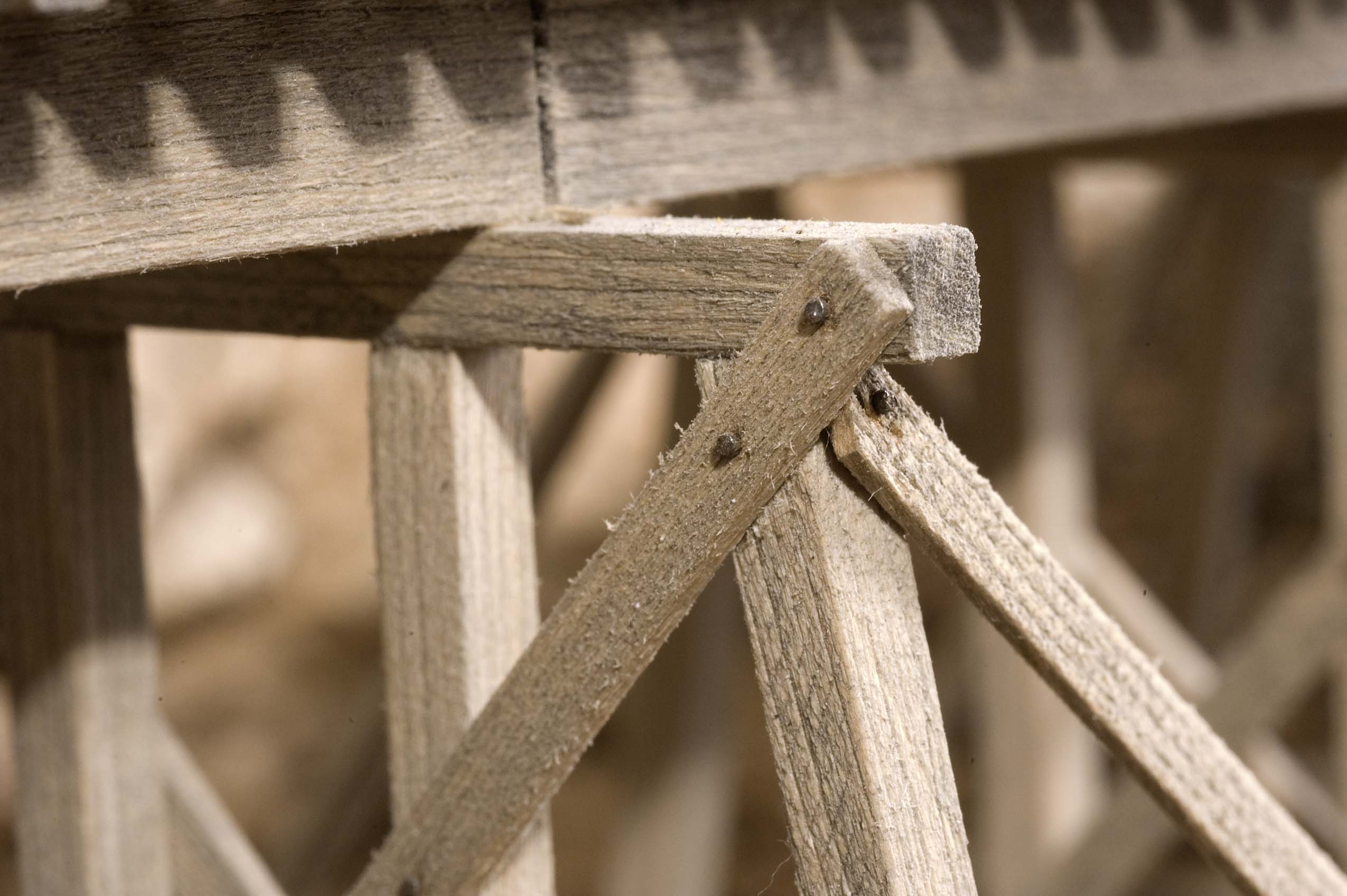 Photo 24 The stringers were made in a prototypical manner using three 8" x 24" x 15' long timbers separated by thin spacers. Their ends were butted together with a slight angle to account for the curving track. Diagonal bracing was glued and attached with small brads. |
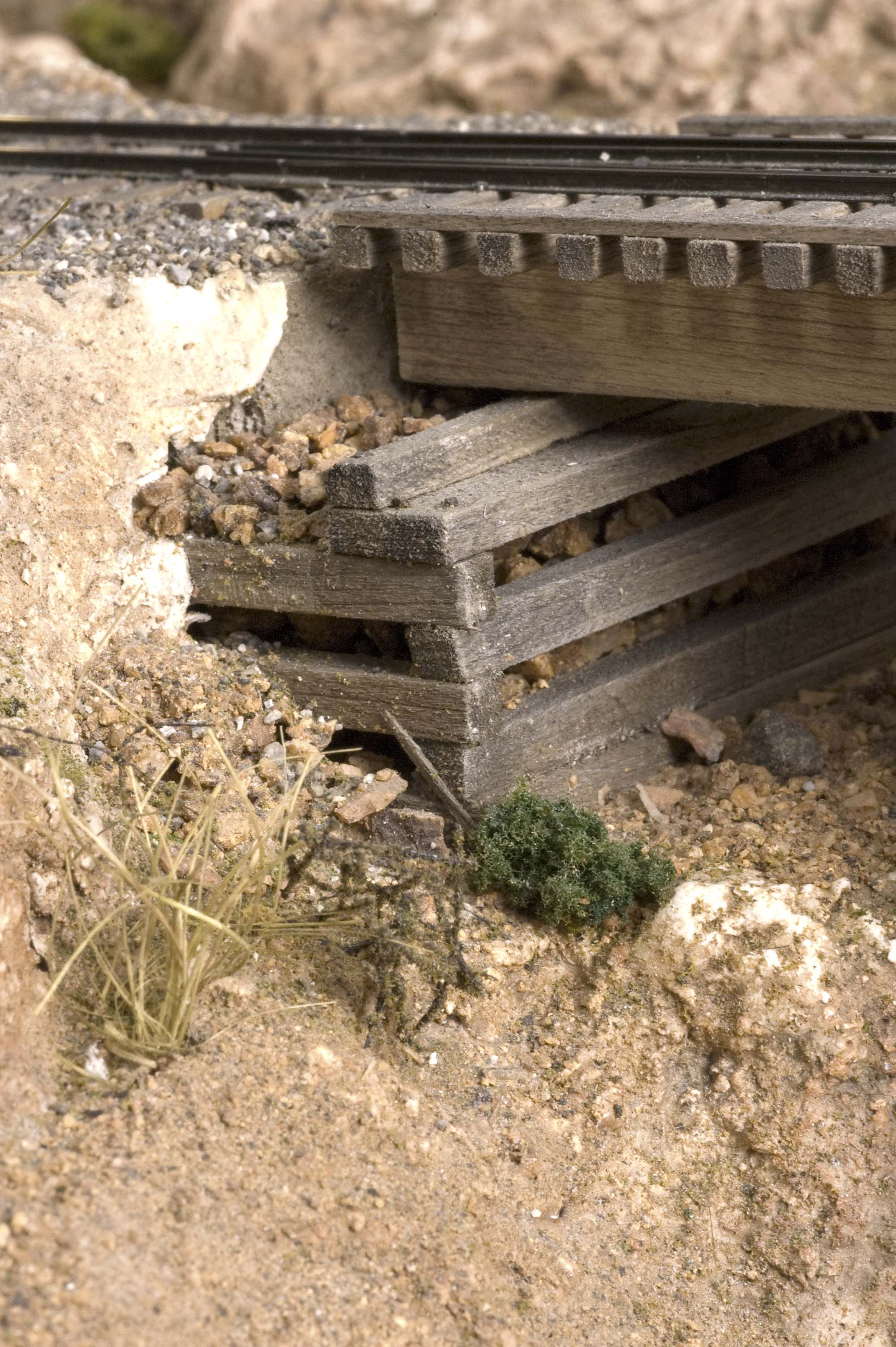 Photo 25 One abutment was built with interlocked stacked ties, then filled with large rock. | 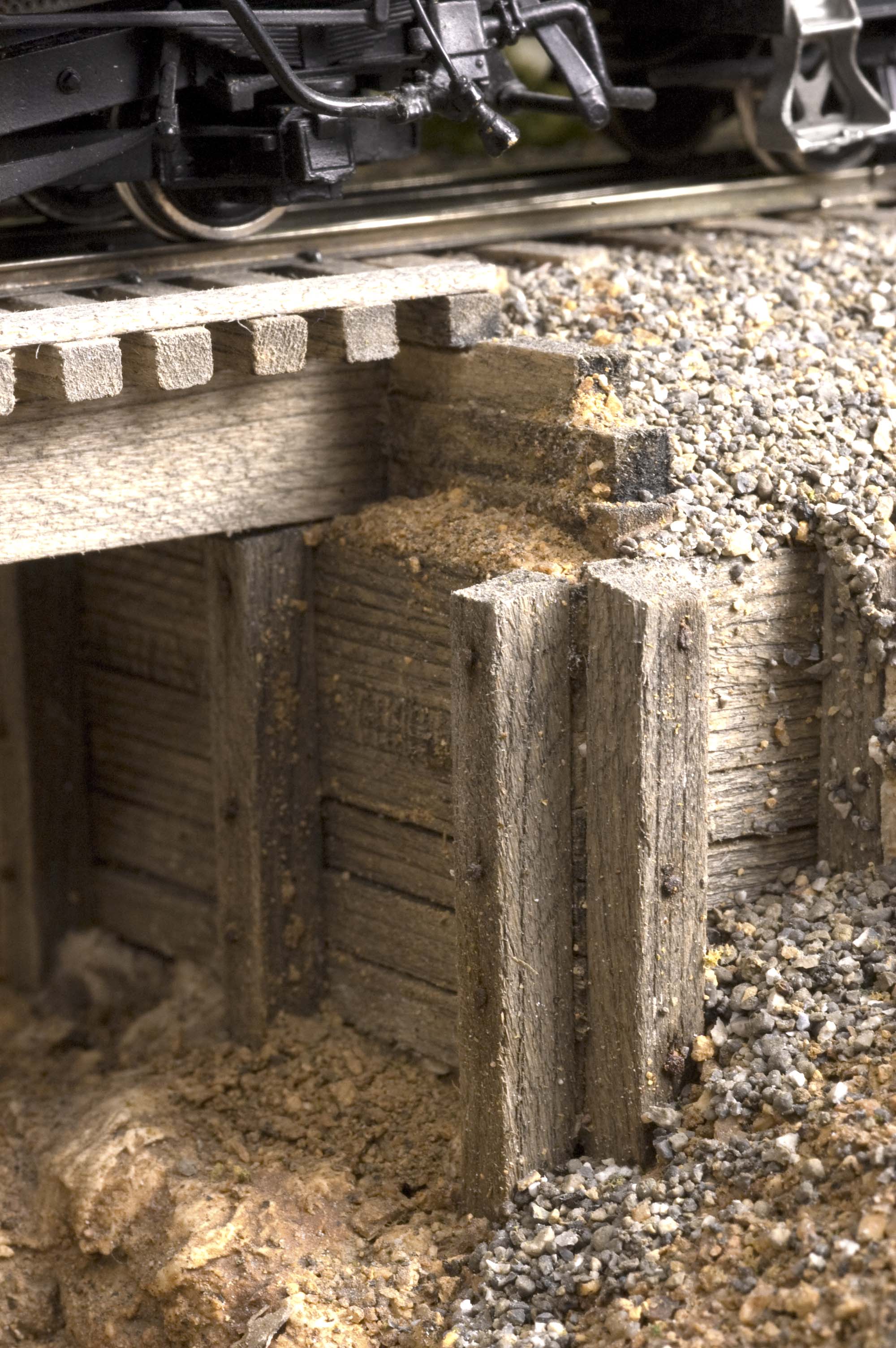 Photo 26 The other abutment was was built in place by gluing 12" x 12" square timbers together, one atop the other, then pinning them with the small brads. The open space behind them was filled with crushed rock and glued in place with diluted white glue. |
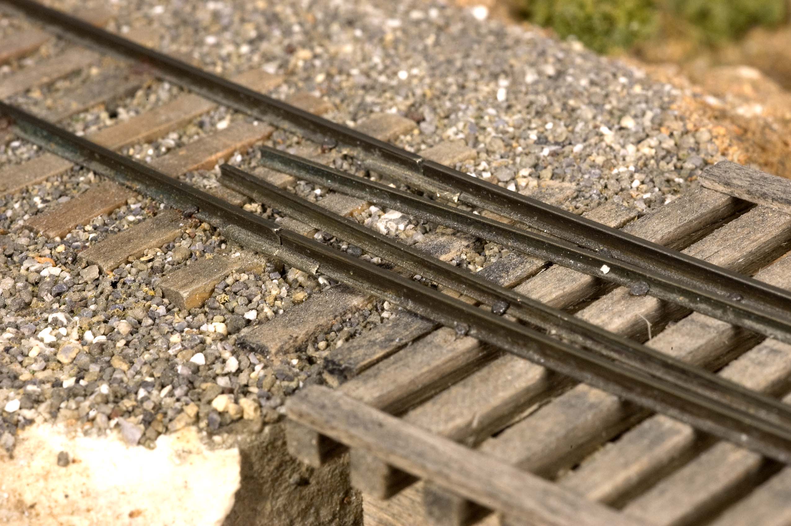 Photo 27 The ends of the rail extend about 2" beyond the ends of the trestle. | 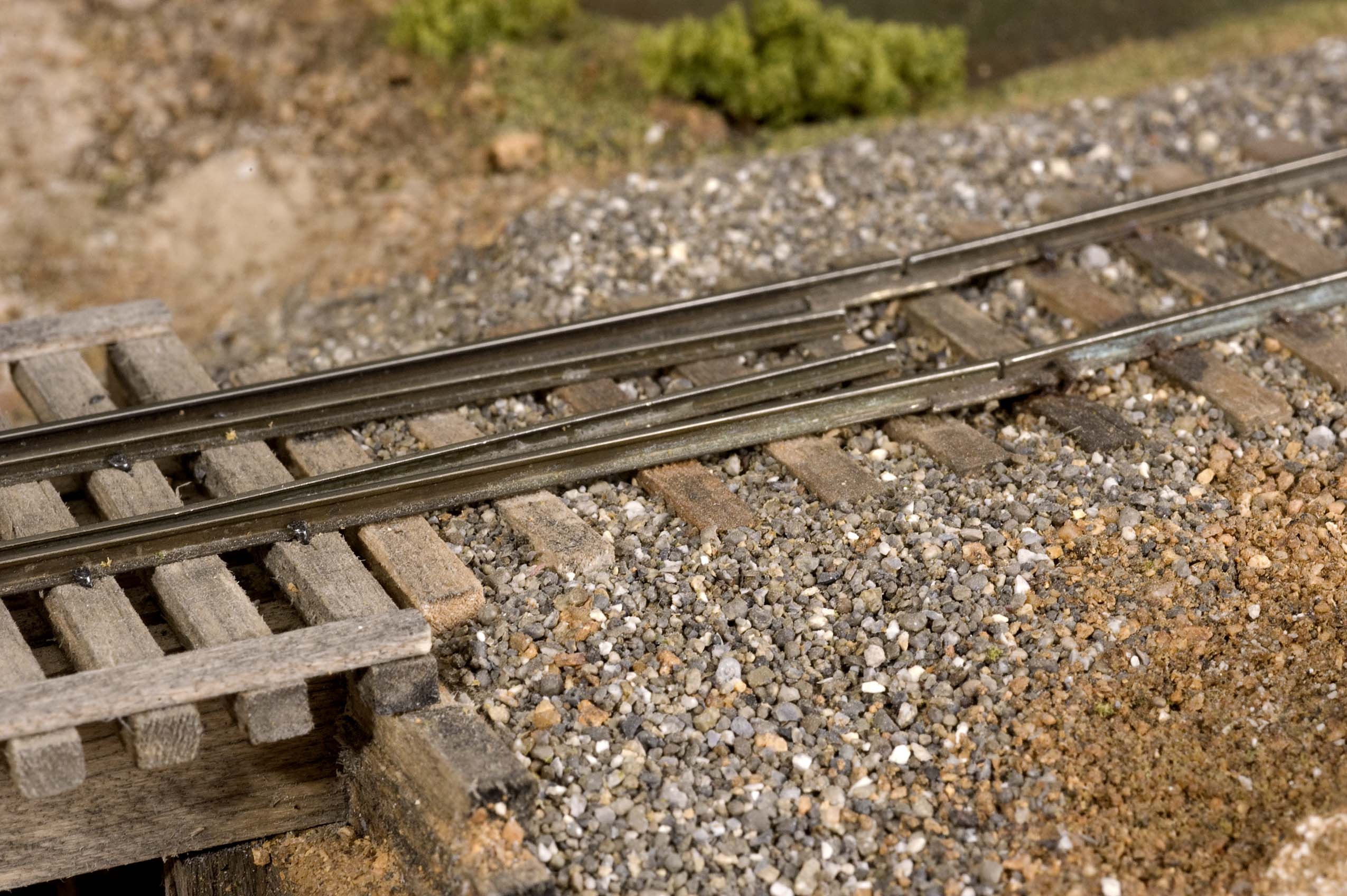 Photo 28 The extra rail length allows for a smooth transition from the ground to the trestle. |
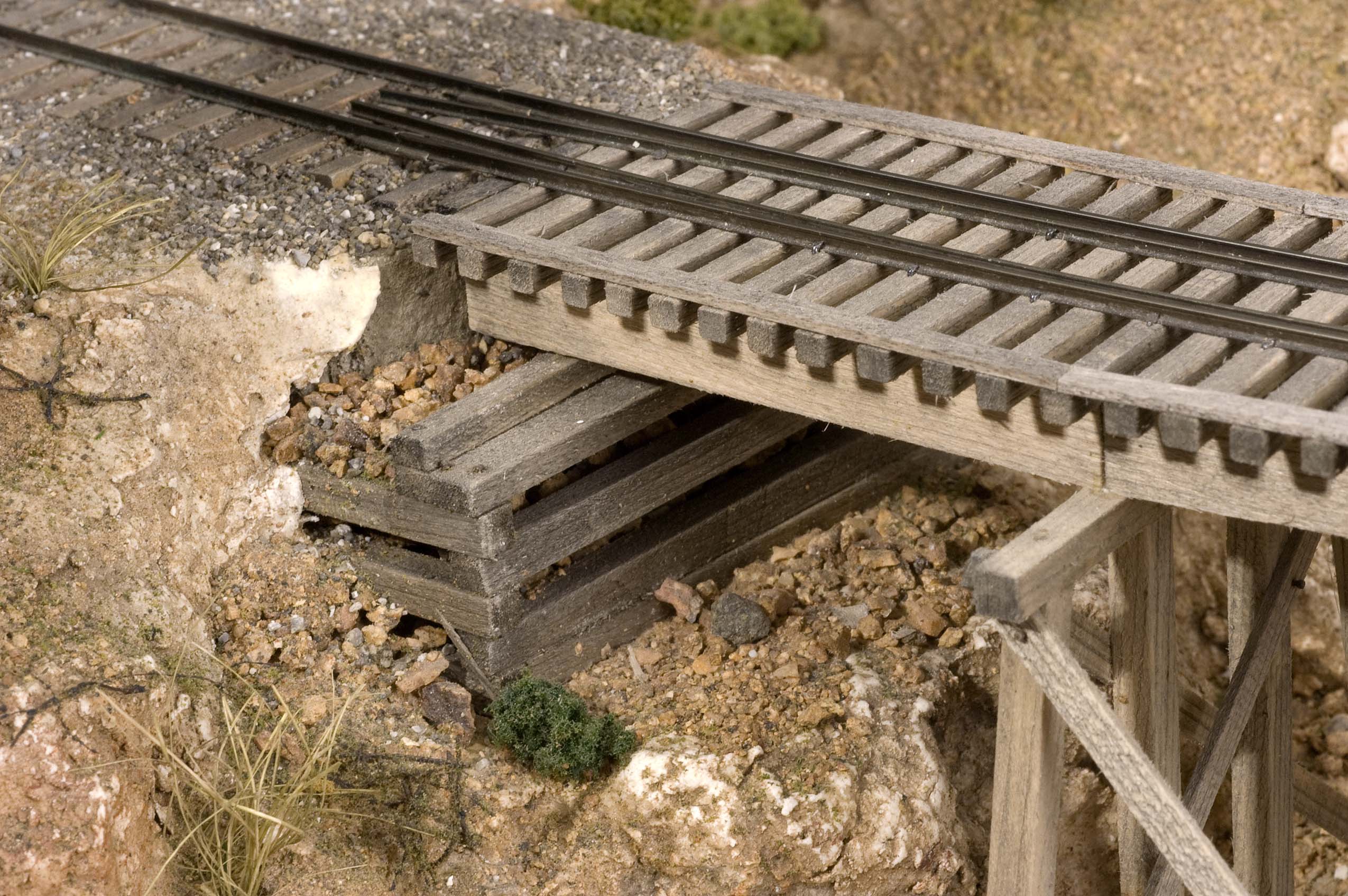 Photo 29 It's apparent from this photo that I didn't complete the abutment on the left. I still need to add a few timbers to hold back the gound that could give way below the rails. | 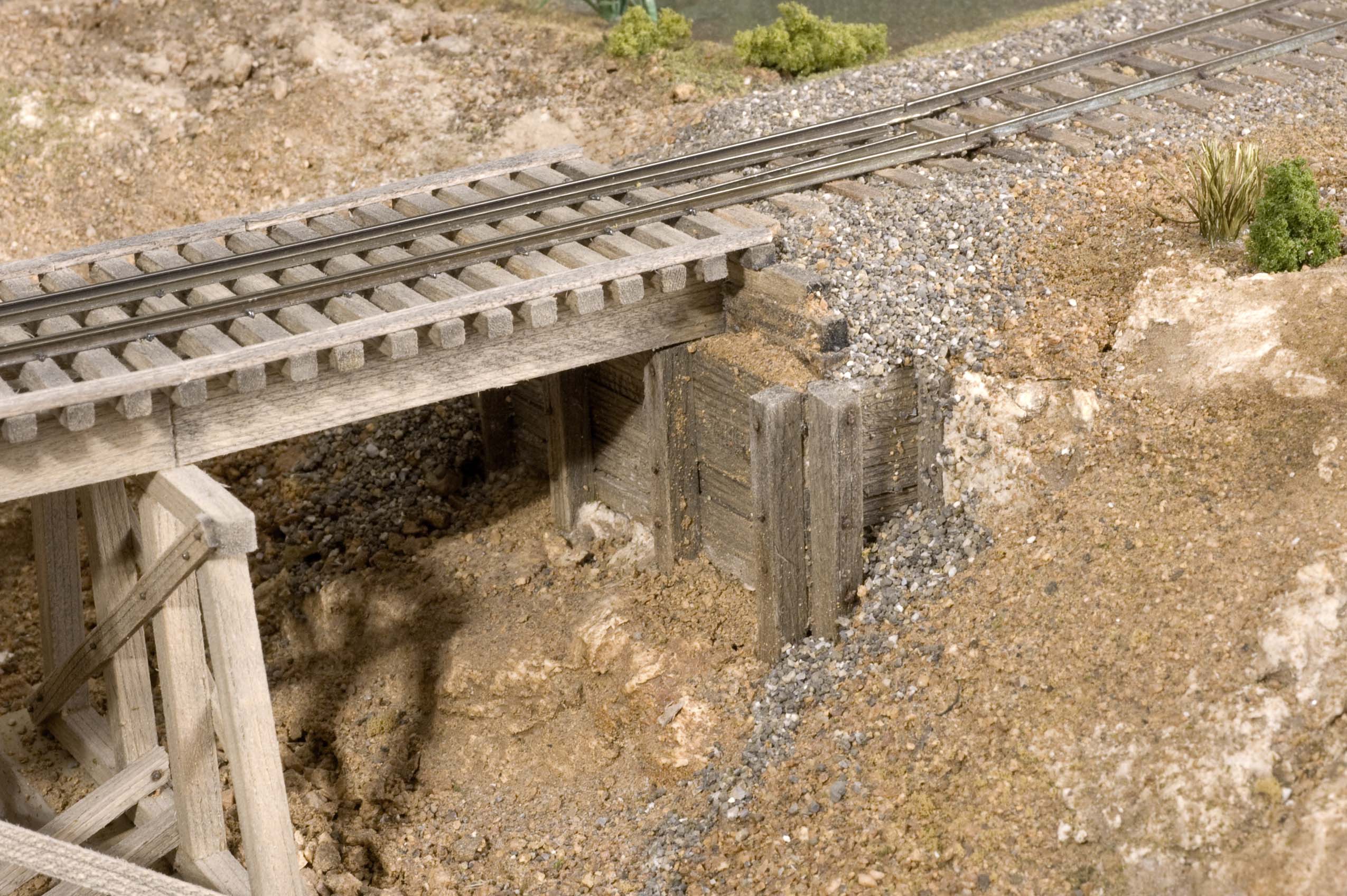 Photo 30 The other abutment appears to be doing its job of prevent erosion of the roadbed below the ties and rail. |
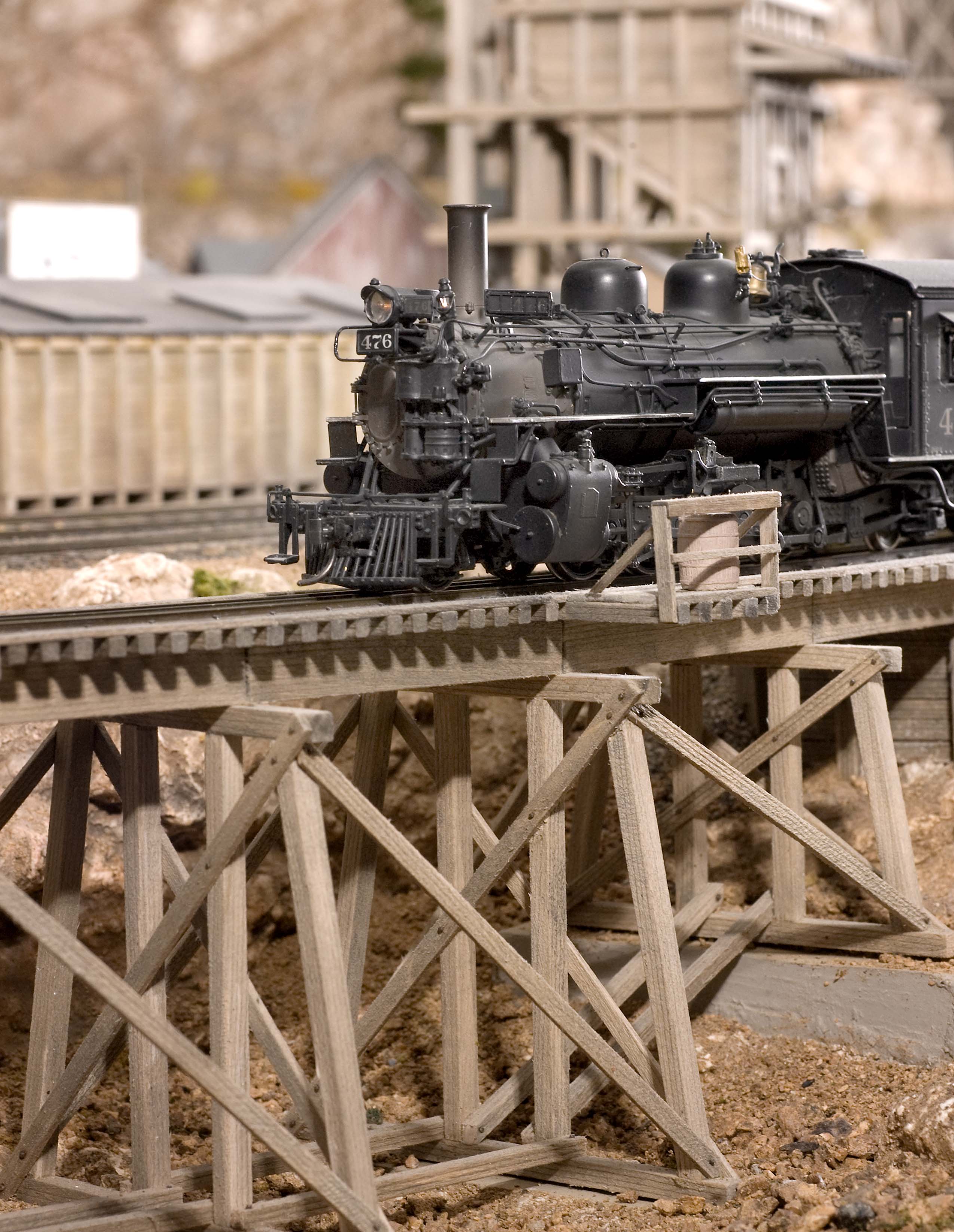 Photo 31 Engine 476 is seen crossing a short trestle as it approaches the community of Tall Timbers. | |
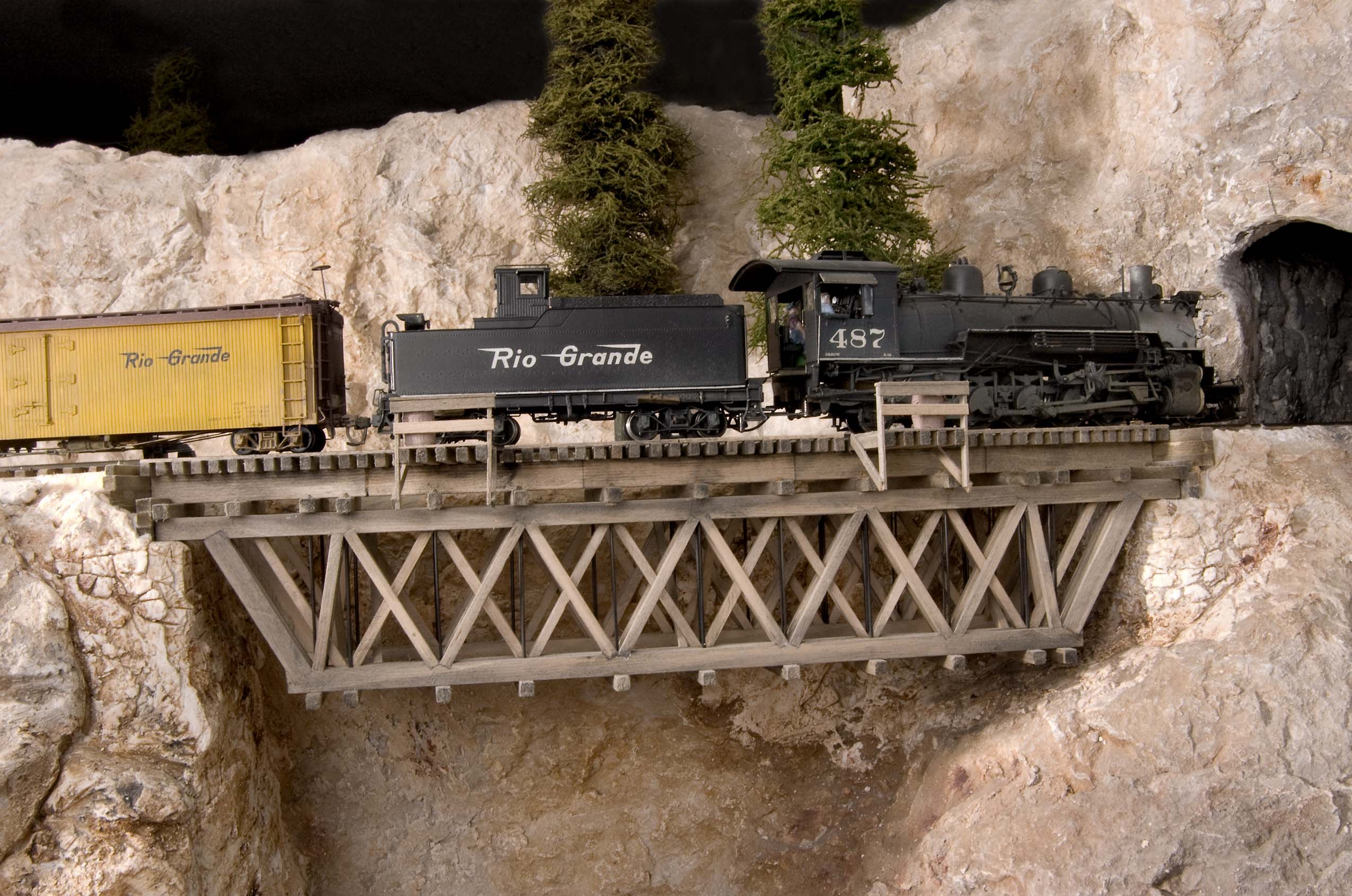 Photo 32 The trestle above Ponderosa Junction spans a short canyon and is supported by hand carved rock abutments at each end. While the actual truss portion is straight, the track is in the easement portion of a 30" radius curve. | 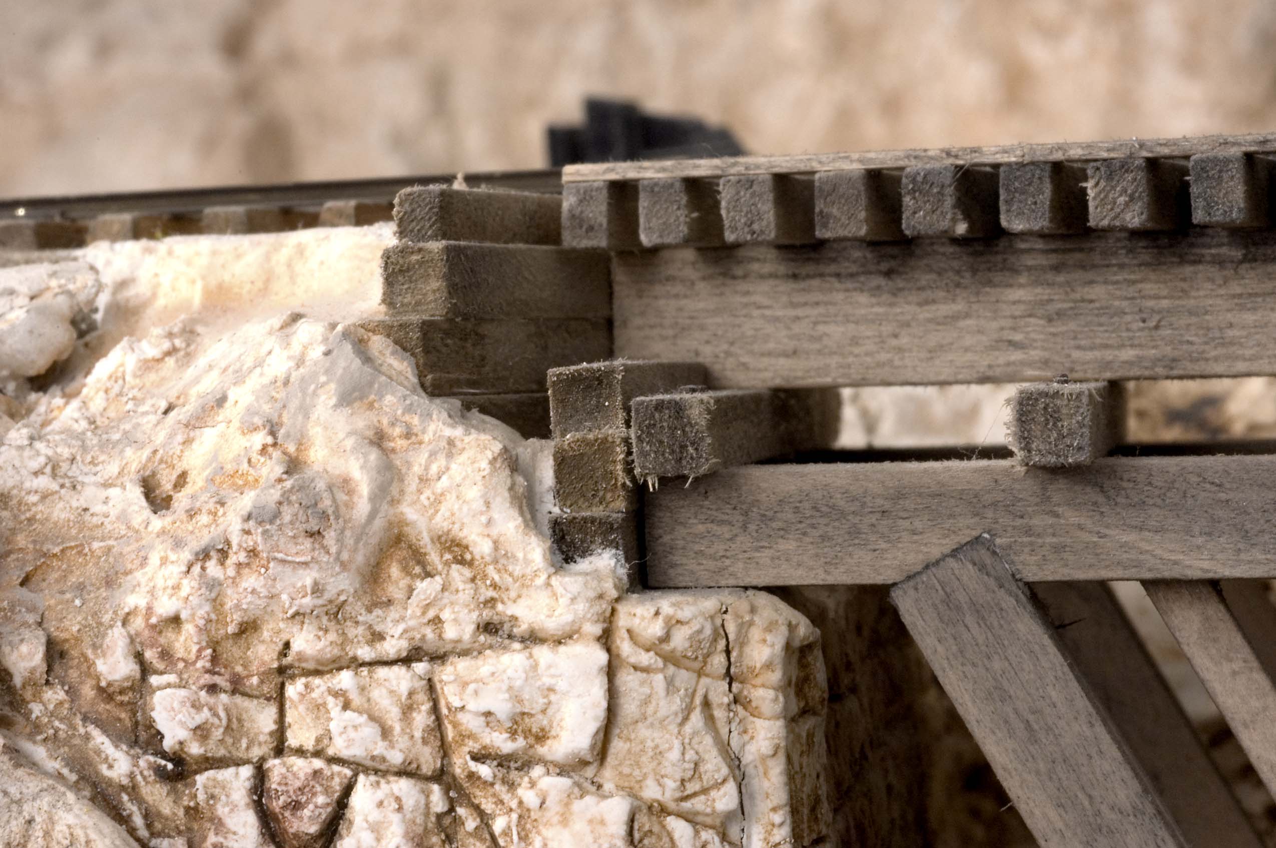 Photo 33 The abutments for the trestle above Ponderosa Jct. still need additional ground cover to be complete. |
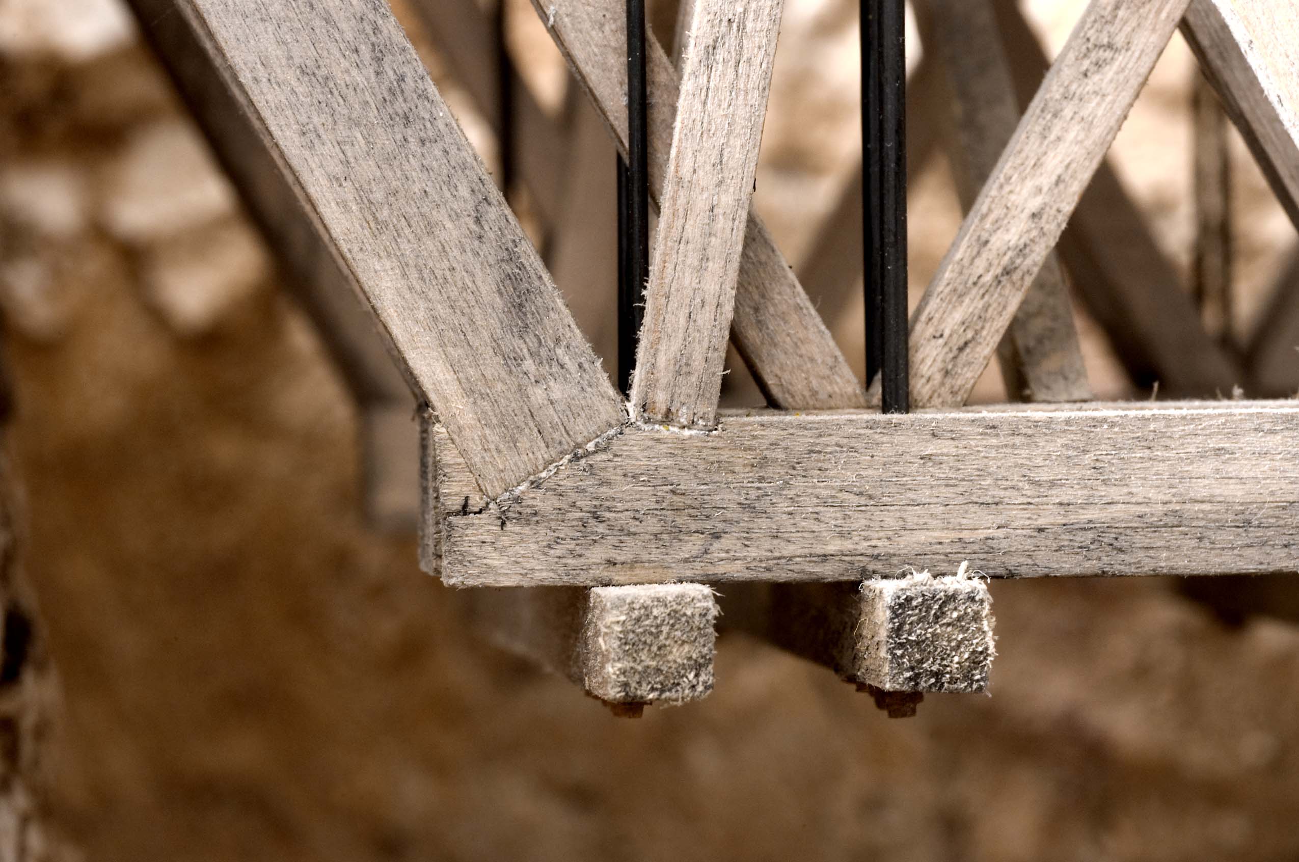 Photo 34 The details to note on this close up view is how the ends of the diagonal timbers are angled and set into notches cut into their respective chords. This detail was only done on the front visible side assembly while the diagonal elements for the other side pieces were simply butt jointed together. | 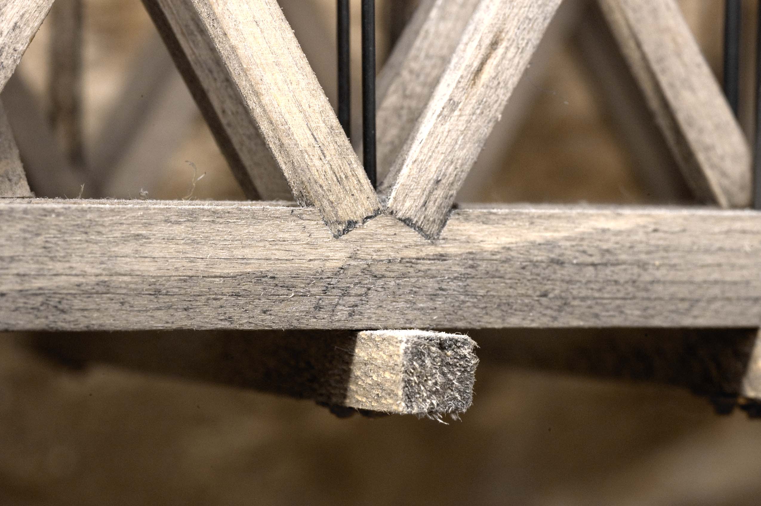 Photo 35 Here's another close-up view of the notching technique used on an intermediate set of diagonals. |
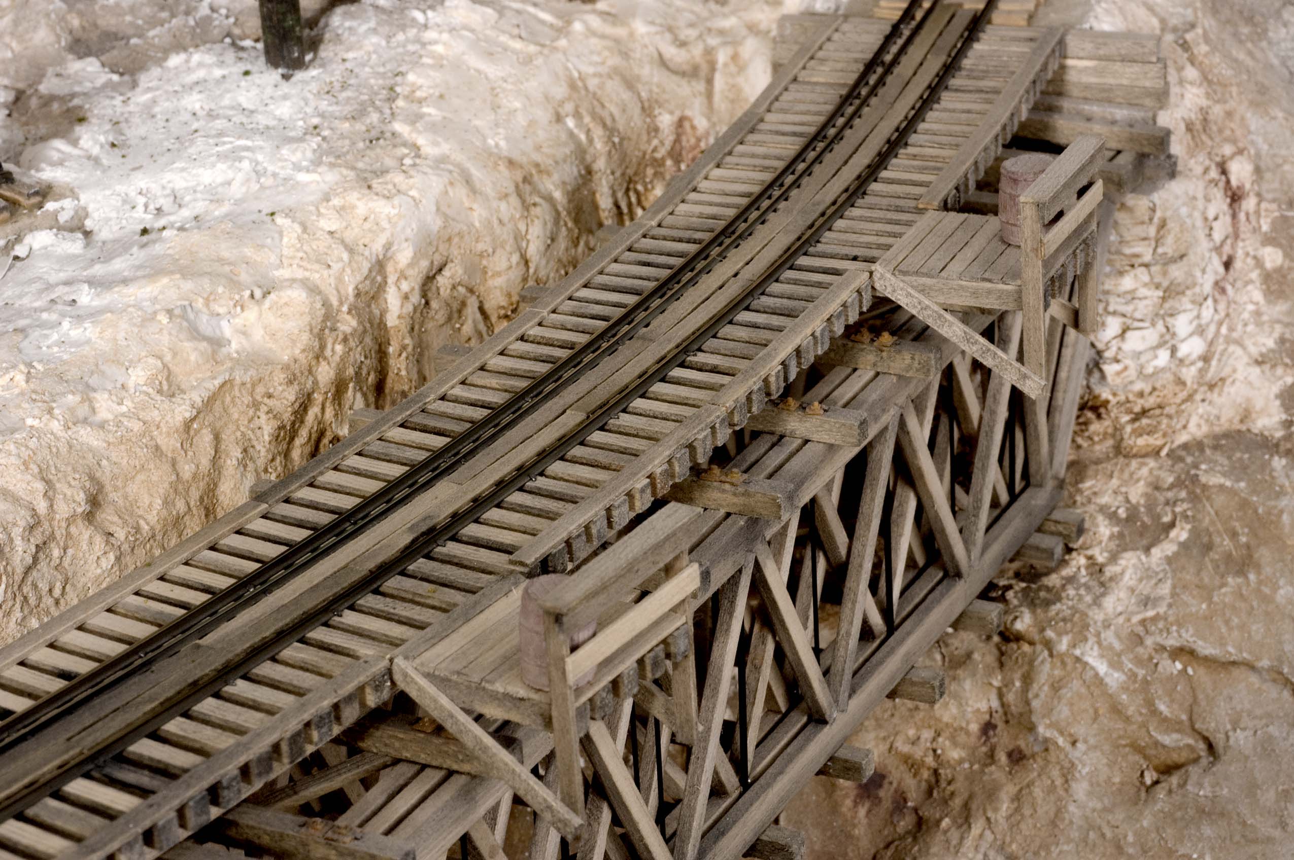 Photo 36 The gentle curve over the trestle is clearly visible here. Besides the stand-offs for the fire barrels, planking boards has been laid between the rails for track workers to safely cross from end to end. | 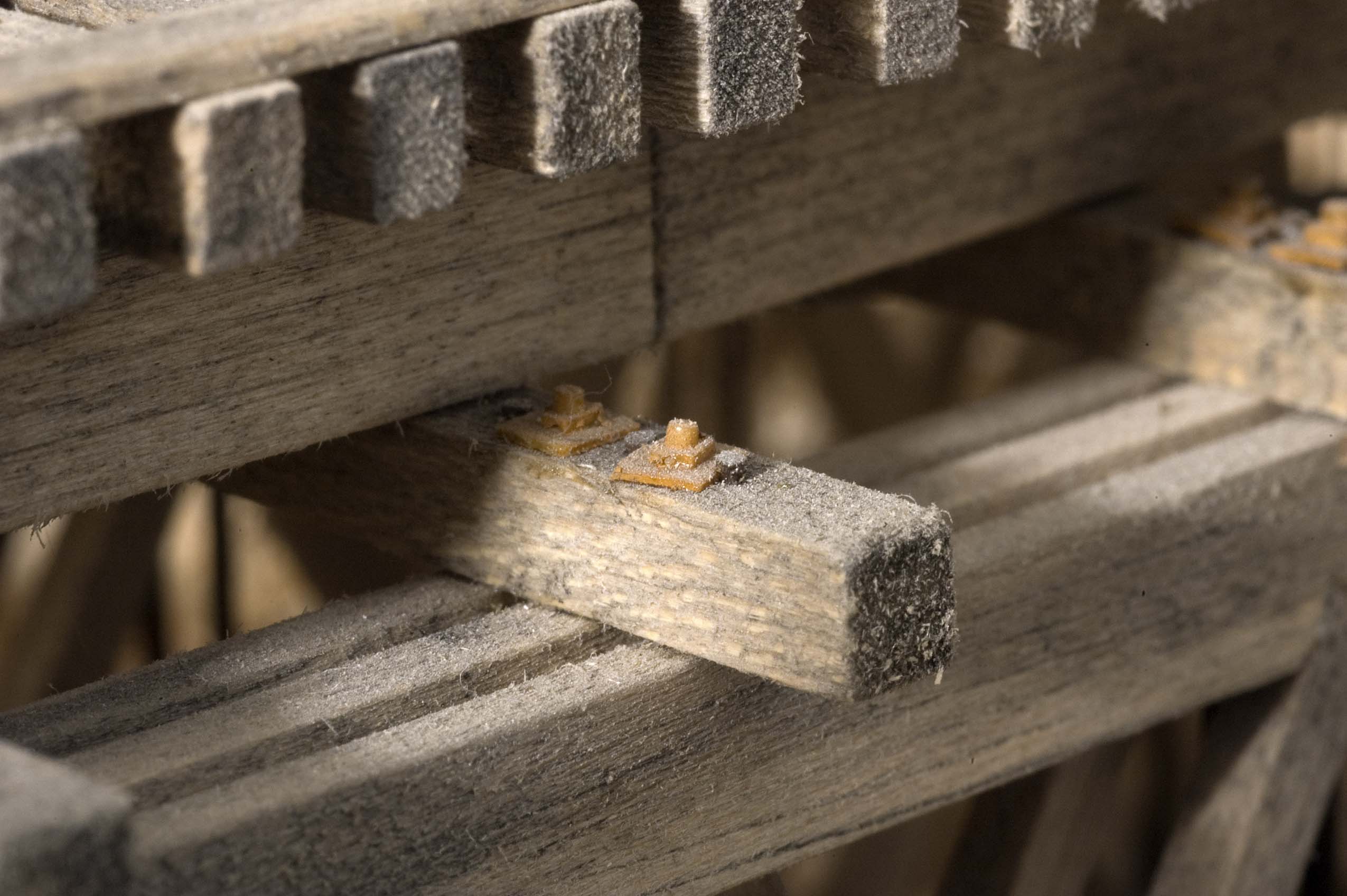 Photo 37 The scratchbuilt NBW castings were made with 5-minute Epoxy and glued to the cross members with CA. They hide the ends of the music wires used to represent the connecting rods. |
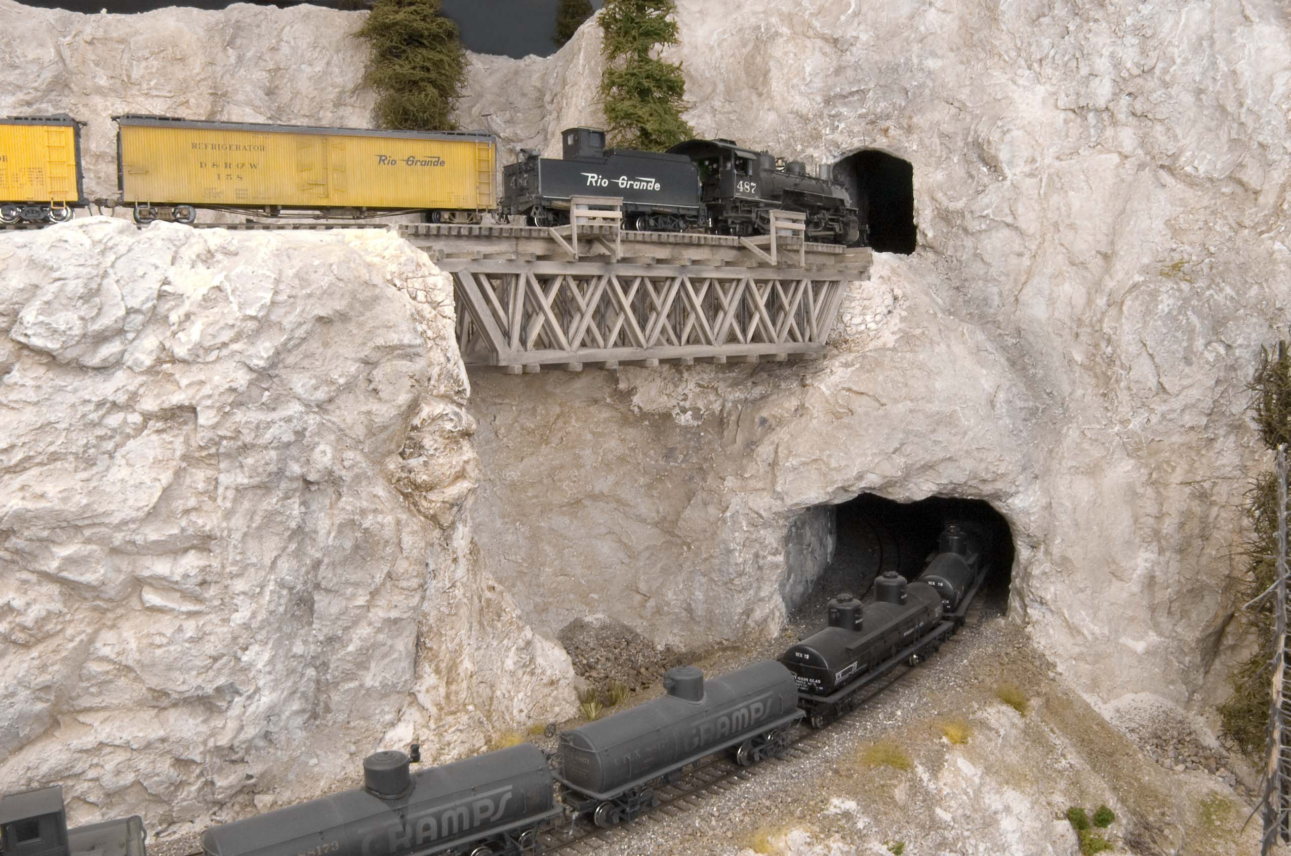 Photo 38 The underslung open-deck, Warren Truss trestle above Ponderosa Jct was one of the last trestles constructed on the layout. Like some of the others, it was also built for a slightly curving track alignmnet and is about 73 scale feet in length. | 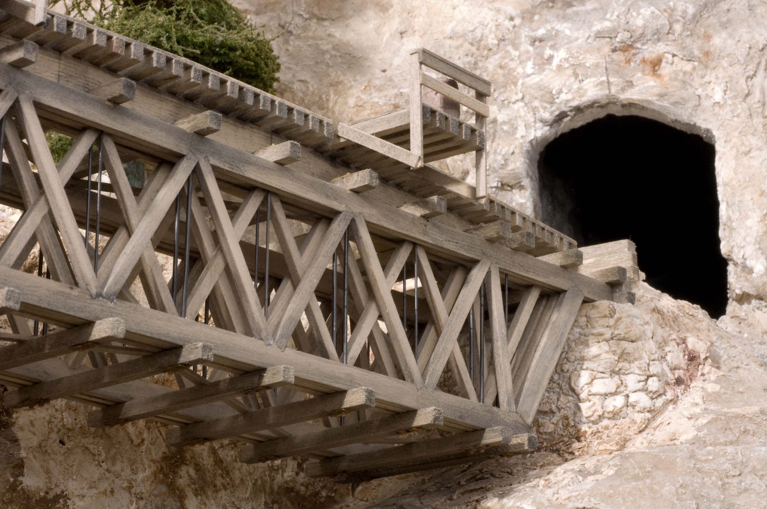 Photo 39 In this underside view of the Warren Truss span, it's still evident that ground cover needs to be added around the abutments. This bridge is part of the reversing loop on the upper level of the layout. |
 Photo 40 One of the largest and most photographed trestles on the layout is this one at Cimarron Canyon. It's a combination Deck Truss and Trestle that was scratch built out of bass wood, music wire, brads, home-made NBW details and code 70 and 55 rail. | 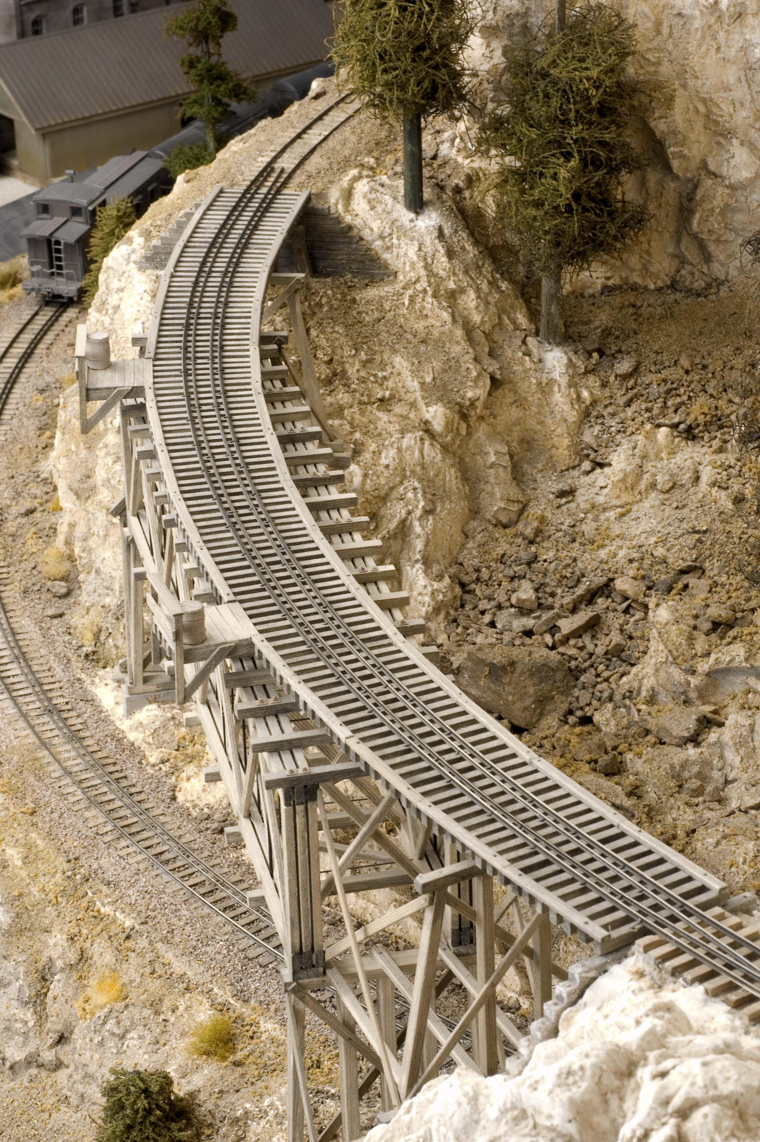 Photo 41 This over head view of the Cimarron Canyon trestle shows that the track shifts from one side to the other as it crosses as it crosses the supporting deck. The width of the deck was designed to take the 30" radius curve into account. |
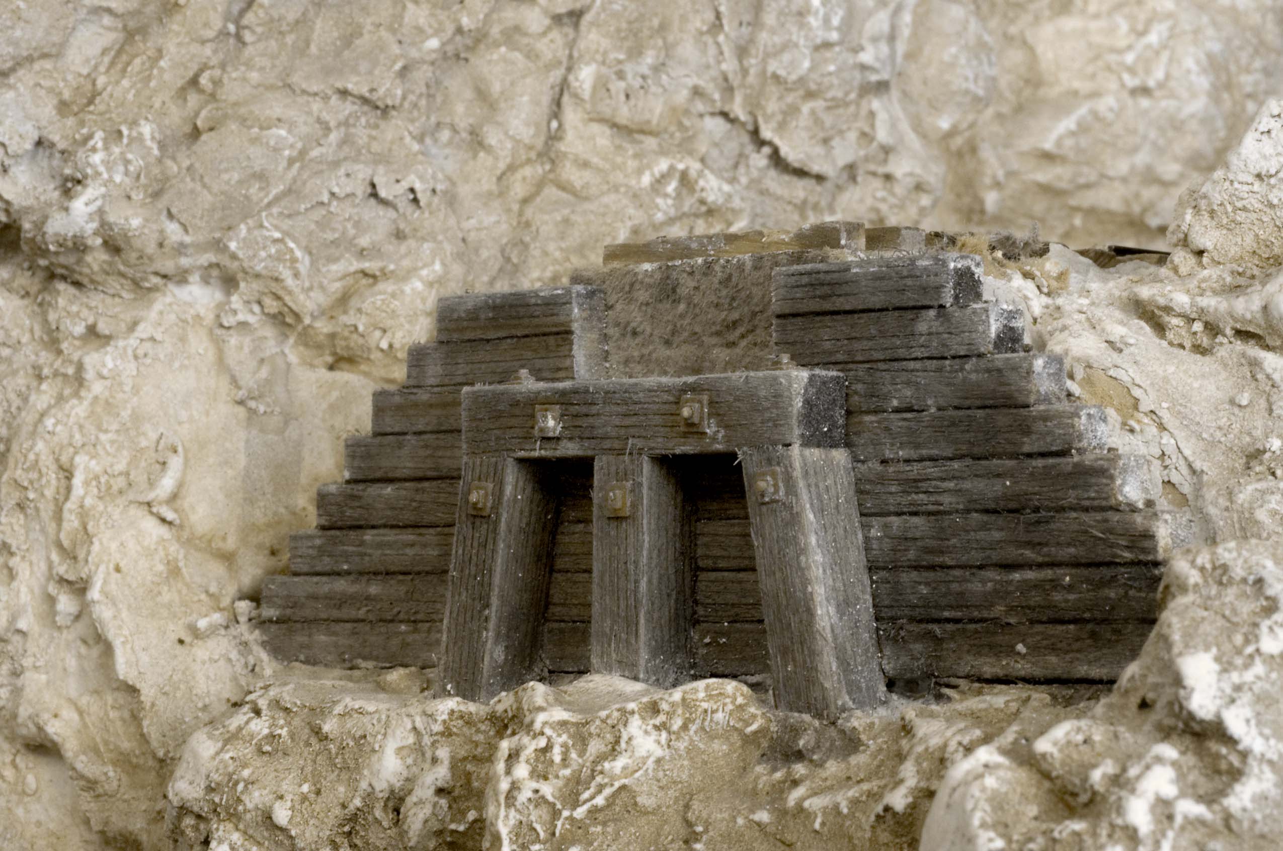 Photo 42 This abutment for the Cimarron Canyon trestle includes an alignment, "key," or notch that makes it very easy to reset the entire trestle structure when it's removed to do scenery work. | 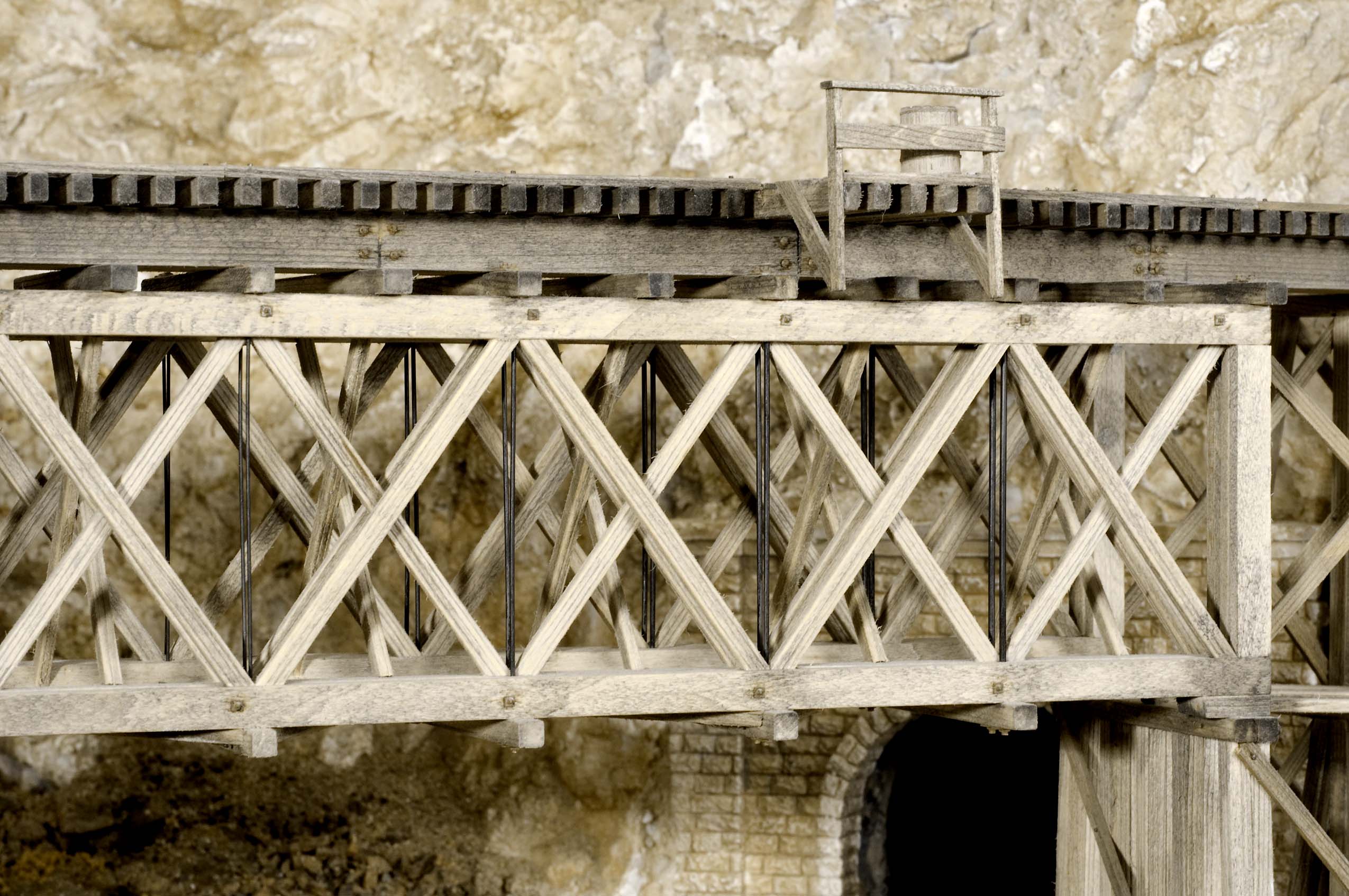 Photo 43 A close look at the truss rods on the Cimarron Canyon trestle will show that they are smaller in diameter at the center and become larger toward the ends as is the prototype practice. |
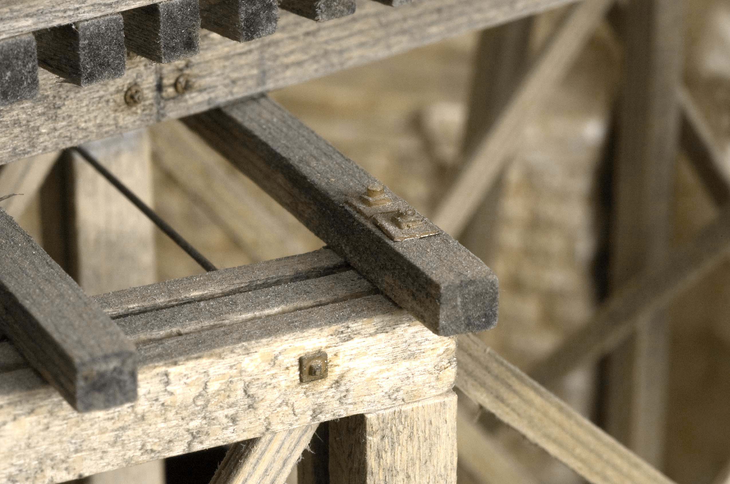 Photo 44 The two large NBW castings on the supporting timber of the Cimarron Canyon trestle were made from RTV molds I made from masters created with scraps of the different diameter wire used for truss rods. Castings were made from, "5-Minute," epoxy and attached with CA adhesive | 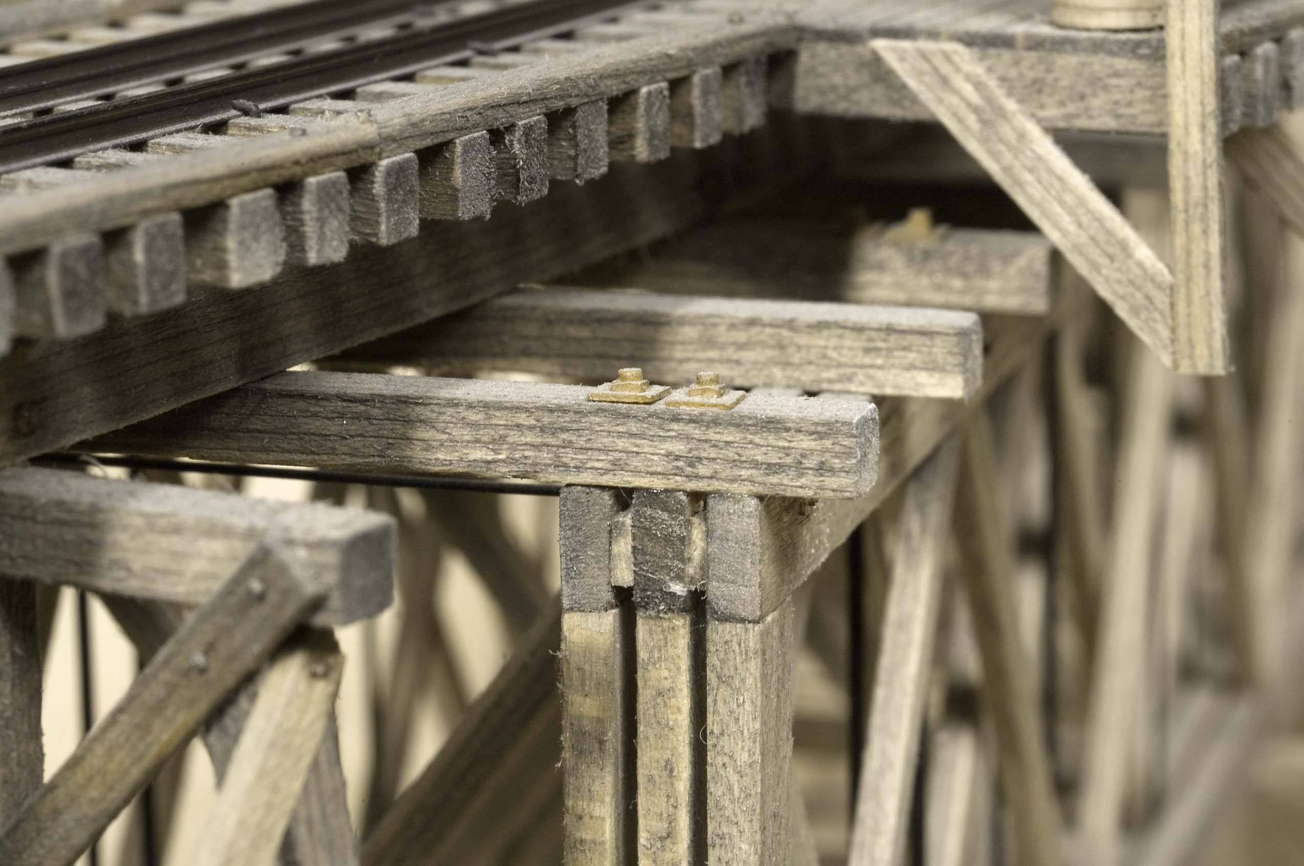 Photo 45 This close up view of the Cimarron Canyon trestle clearly shows the home-made epoxy NBW castings as well as the three assemblies that make up each side of the truss span. The space between them was determined by the diameter of the largest truss rod. |
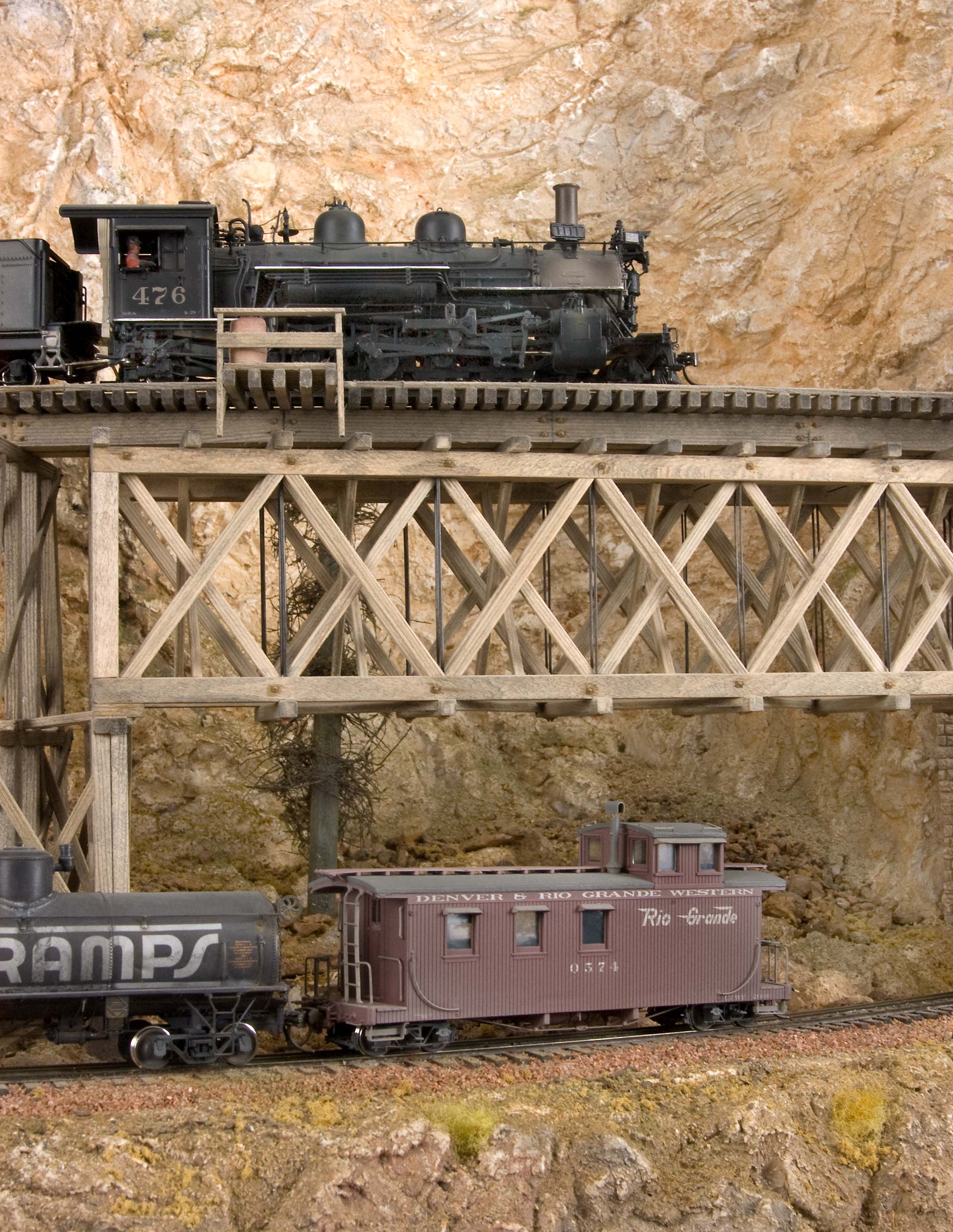 Photo 46 Engine 476 is seen crossing the open deck truss bridge and trestle at Cimarron Canyon. The main line below shows the tail end of a train heading up the grade towards Cimarron Summit. | |
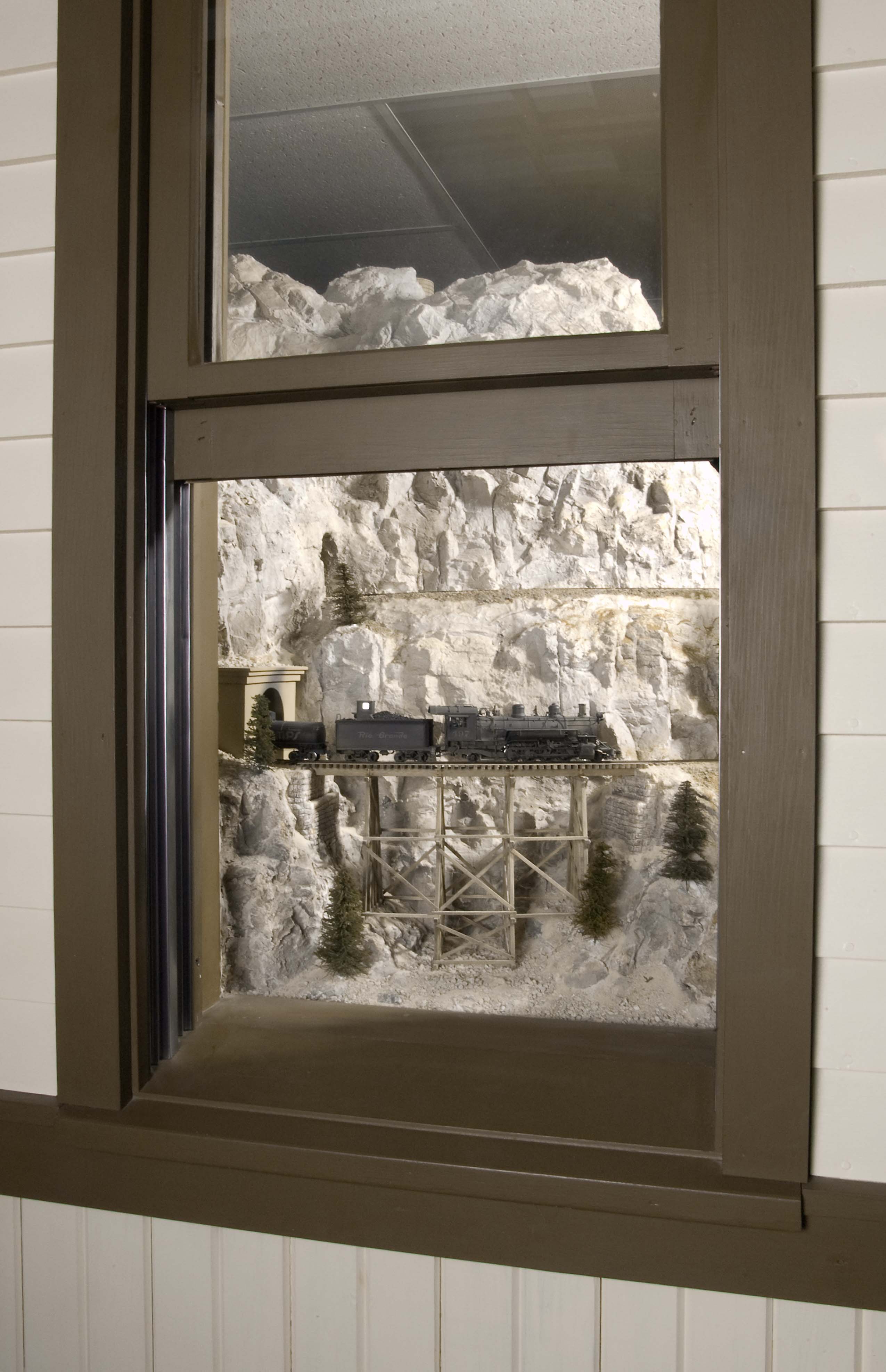 Photo 47 The concrete portal and "Vista Grande," trestle are the prime subjects that can be seen through this window in the layout room wall. | 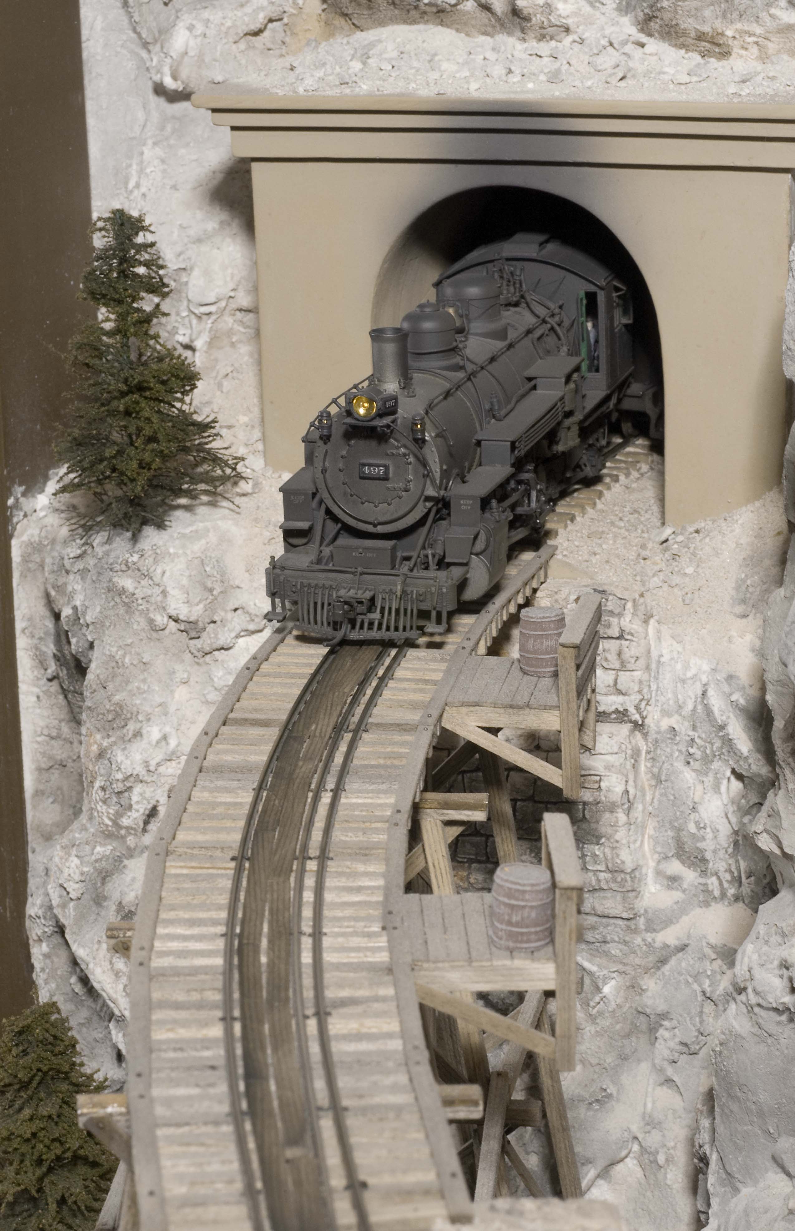 Photo 48 Engine 497 eases out of the concrete portal onto the curved trestle at, "Vista Grande." Note the use of a single guard rail and the double row of planks for workmen to use when crossing the trestle. |
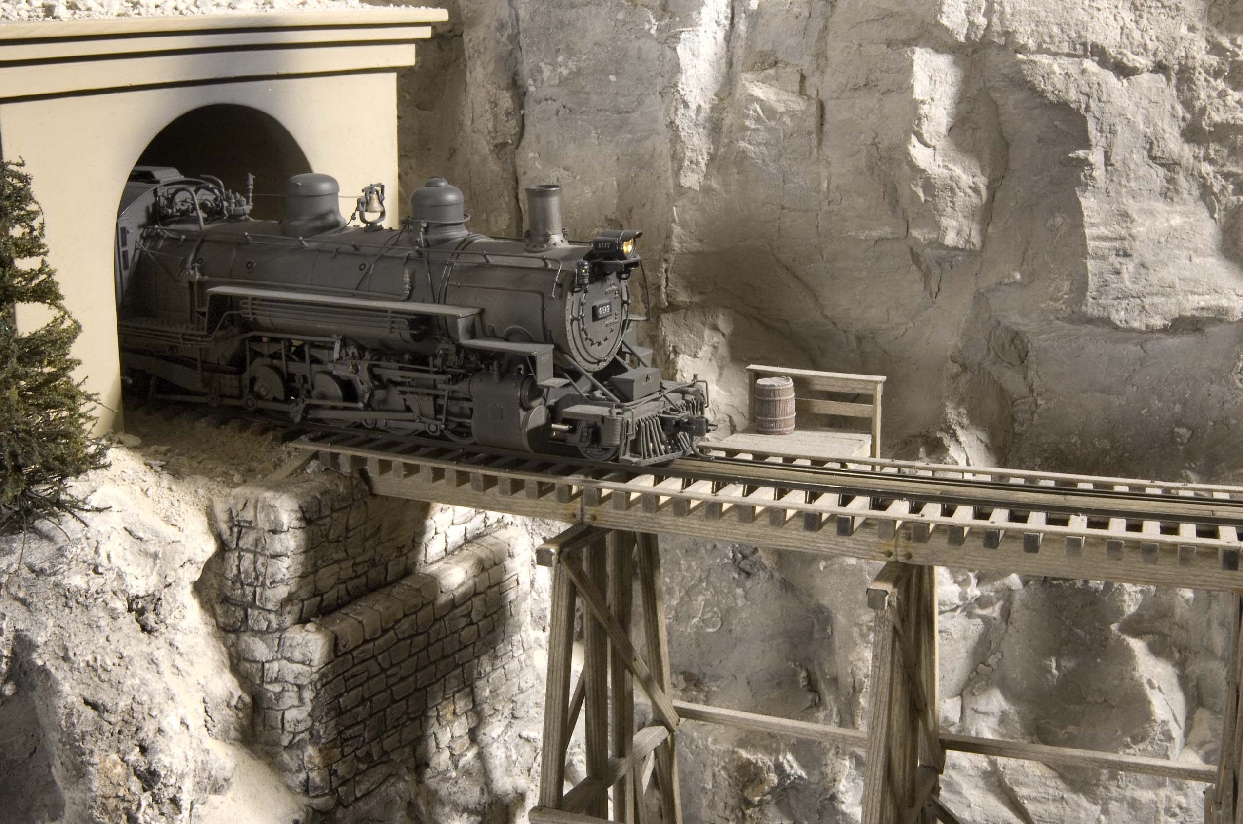 Photo 49 D&RGW Engine #497 has just started its passage over the scratch built, "Vista Grande," trestle. | 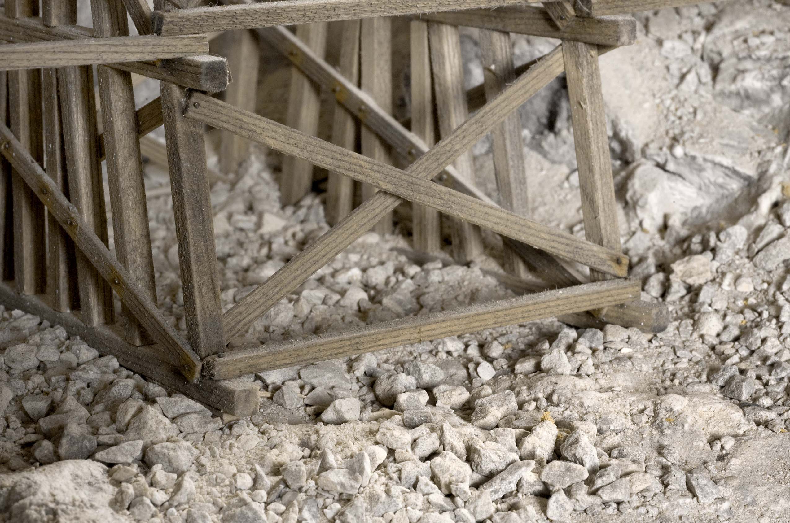 Photo 50 Large 12" square timbers were used as footings for the trestle bents. |
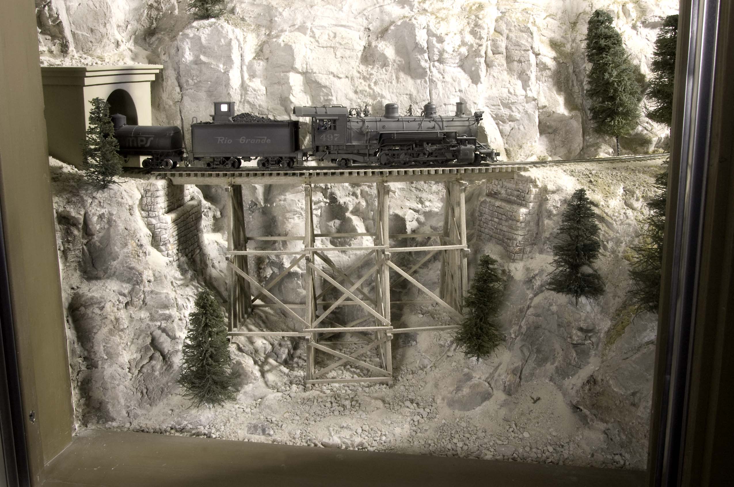 Photo 51 Engine 497 has just exited the concrete portal and has almost completed its journey across, "Vista Grande," trestle on the main line of the C&TT RR. This view is through a window in the layout room wall. | |
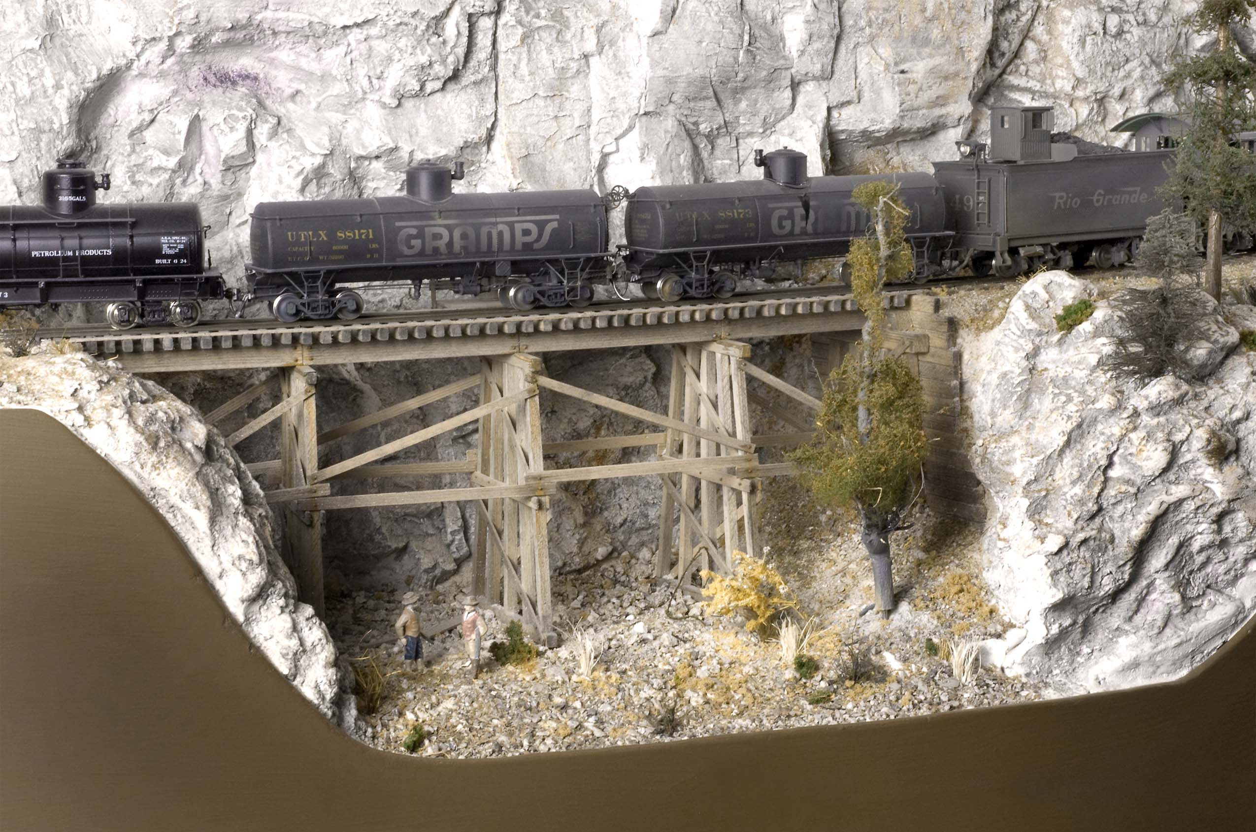 Photo 52 A train of oil cars is crossing the curved timber trestle at, "Bloody Gulch." Track was initially laid across the site, then a few years later the sub-roadbed was carefully removed and replaced with the trestle. | 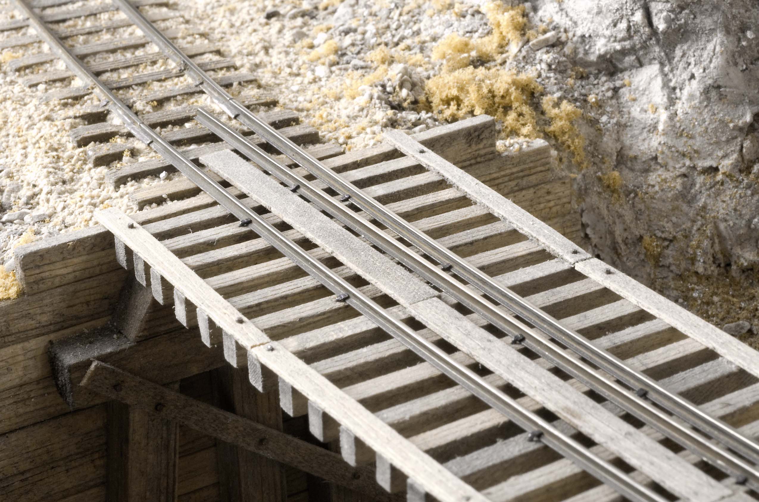 Photo 53 The single row of planks down the center of the track make it easier and safer for track crews to cross the trestle. Note also that the rails extend a short distance beyond the ends of the decking. |
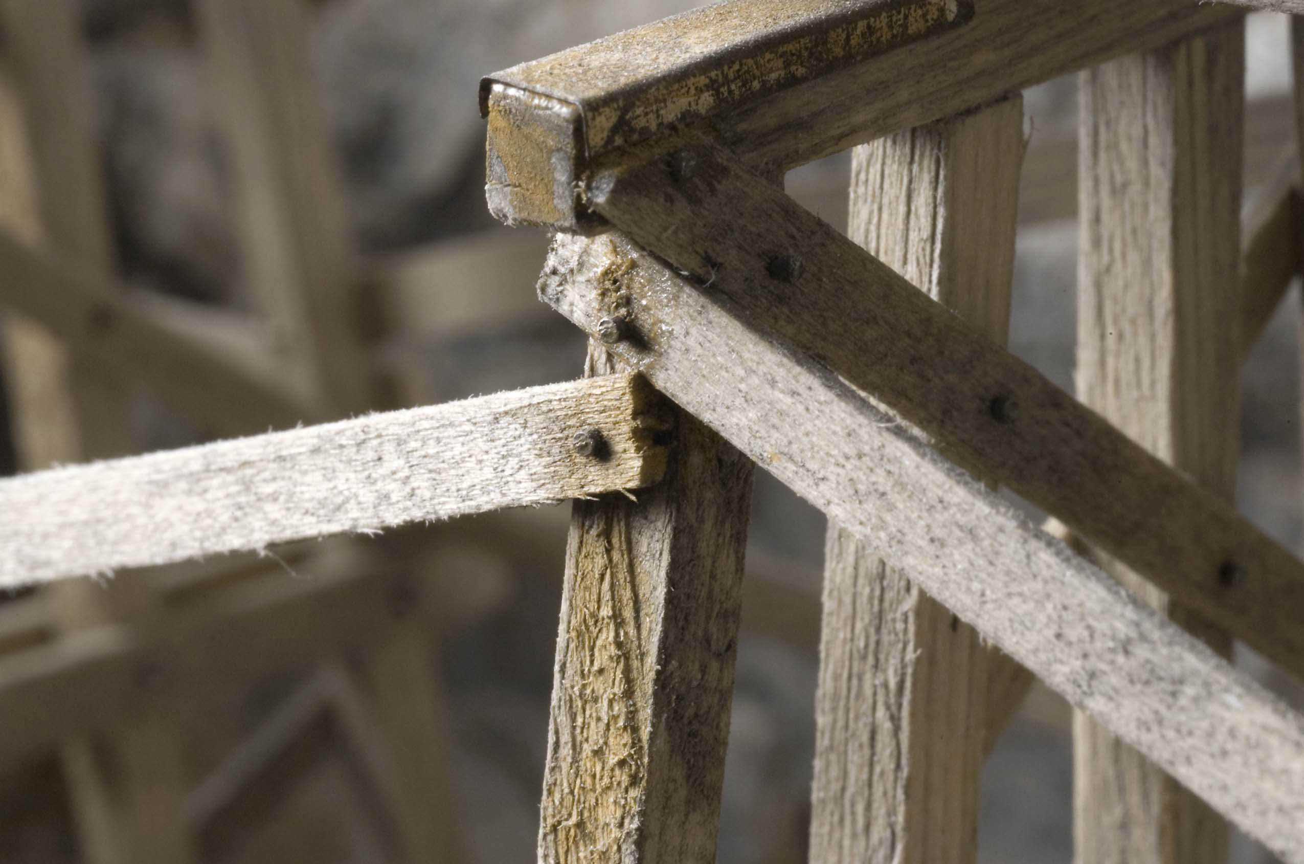 Photo 54 The upper timbers of the trestle have been covered with sheet metal to reduce the chance of them catching fire from hot cinders. The tiny heads of the brads are visible and stained with rust solution to add additional weathering. | 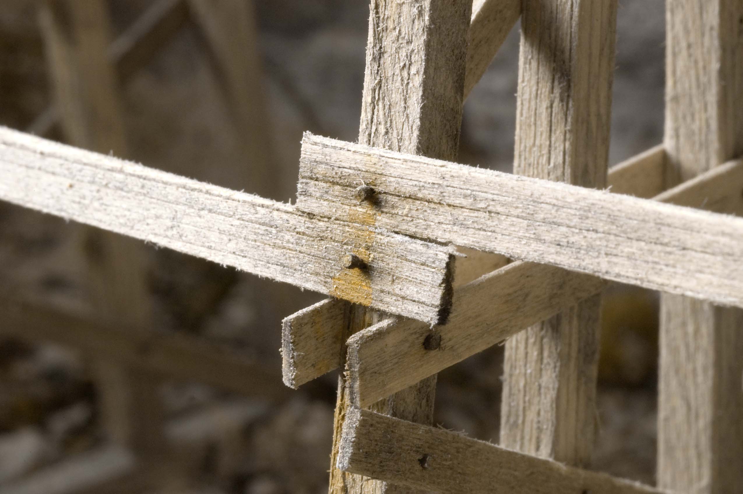 Photo 55 While not exactly looking like a true NBW casting, the tiny heads of brads used to hold the trestle bents together help create the illusion of solid construction. They have been weathered with a wash of a rusty vinegar solution. The tiny heads of the brads are visible and stained with rust solution to add additional weathering |
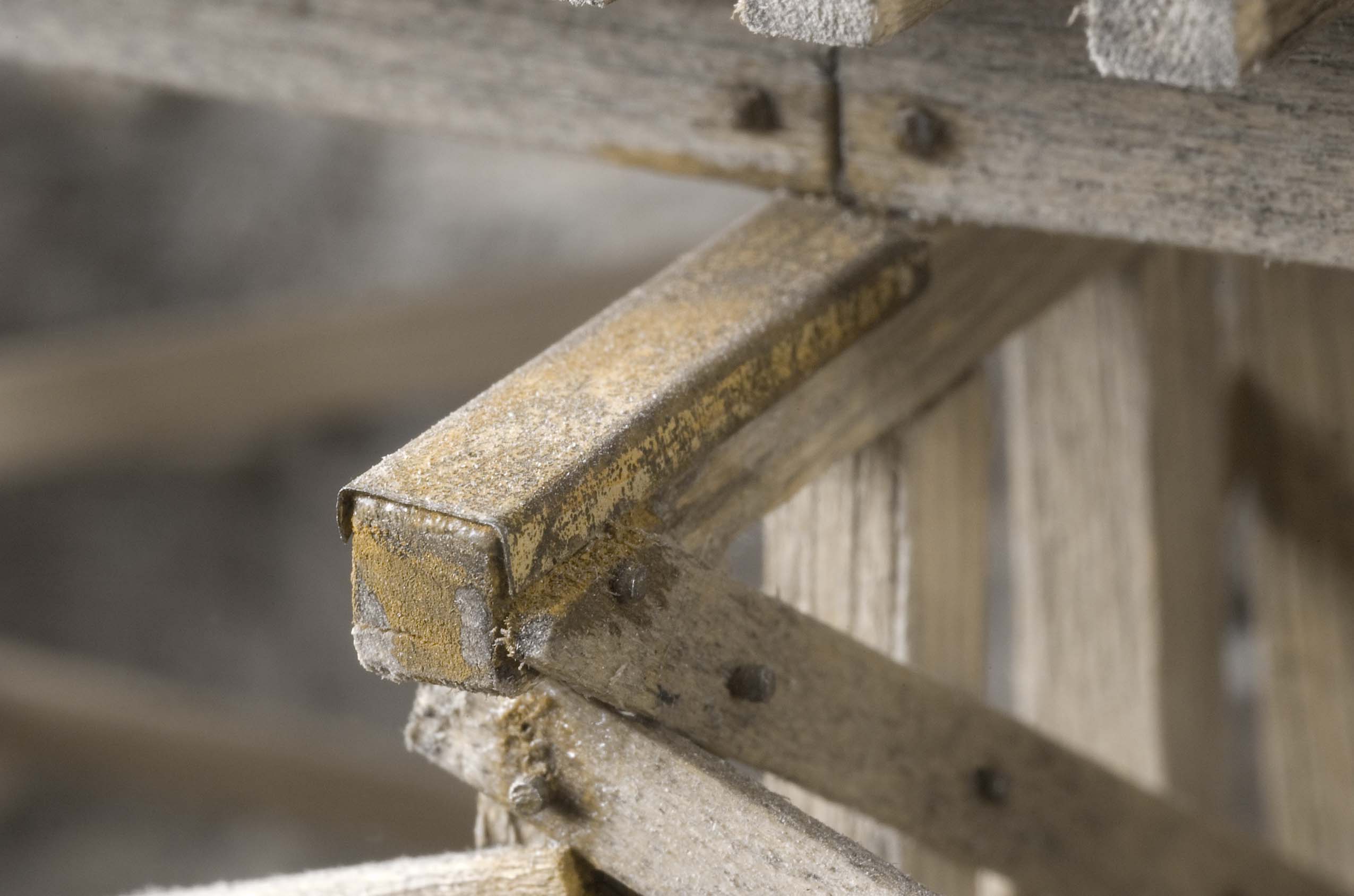 Photo 56 Here's a closer view of the protective metal covering on the timbers that support the stringers. They were made from heavy duty aluminum foil that was etched in a printed circuit etching solution and weathered with a wash of a rusty vinegar solution. | 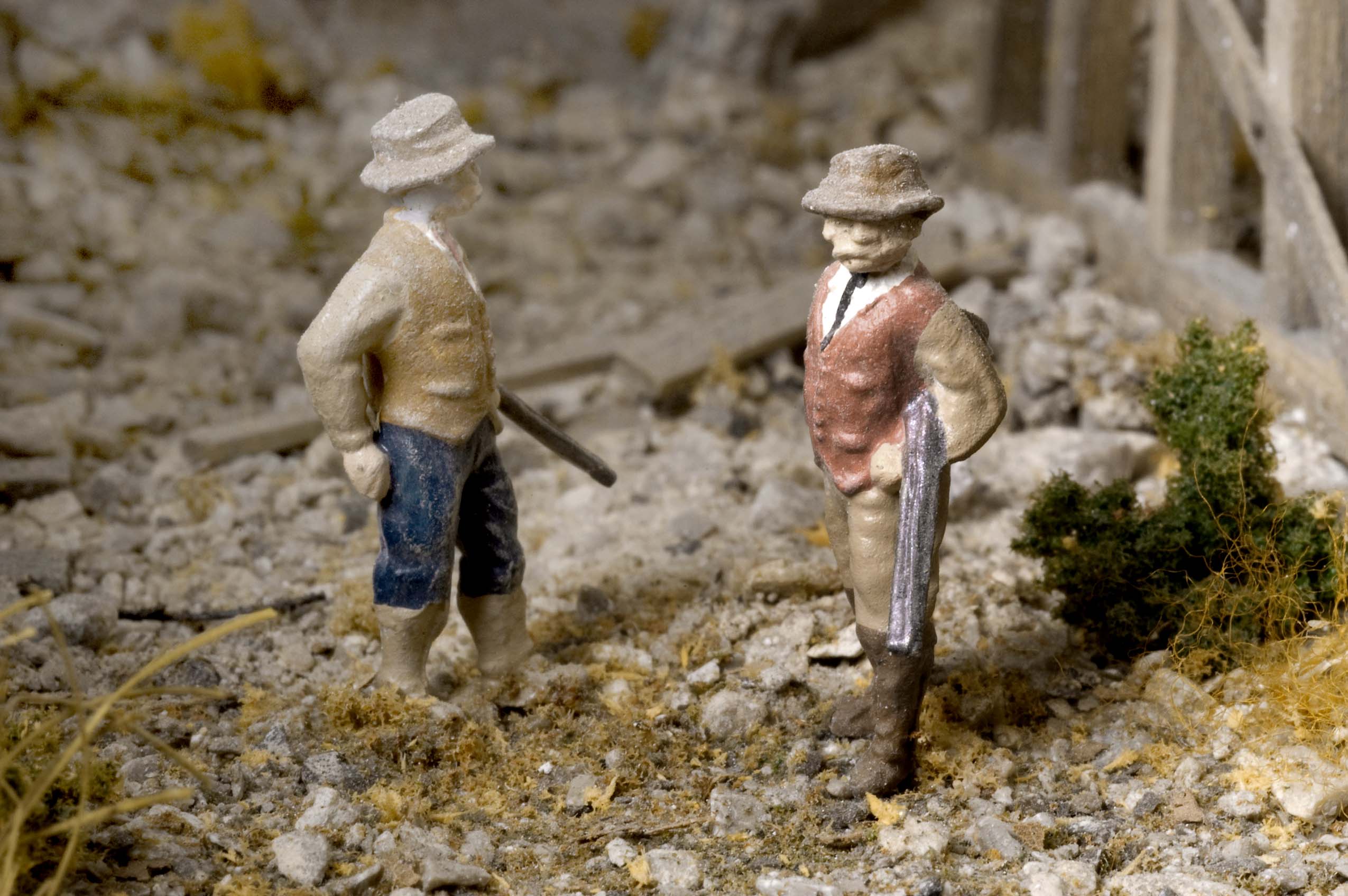 Photo 57 While not directly associated with trestles, these hunters are pausing directly below my Bloody Gulch trestle. While the trestle was being fitted into the site, a slip of an X-acto knife helped me come up with the trestle's name. |
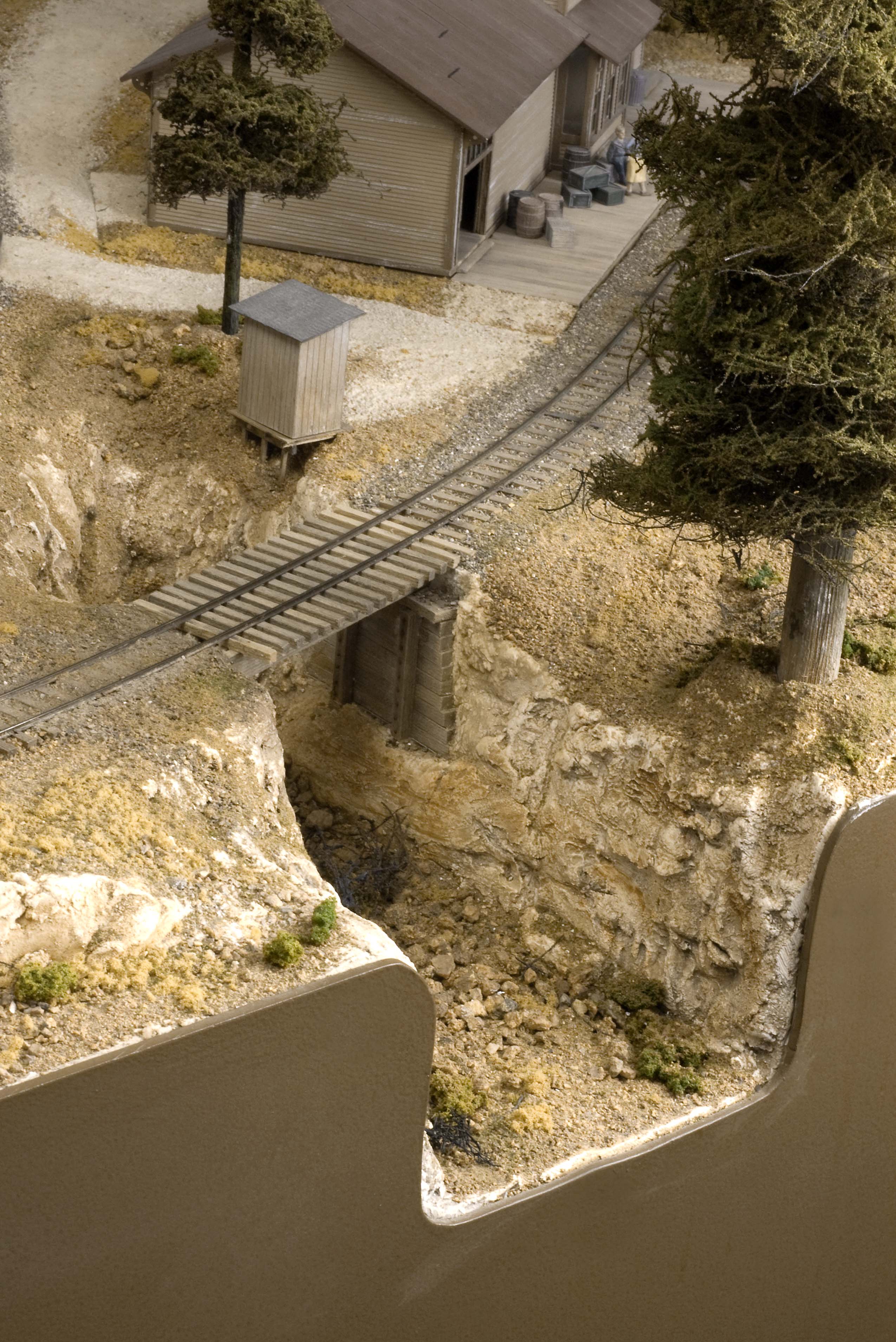 Photo 58 Because the main elevation for the track is 10" above the top of the bench work, I was able to cut an opening in the fascia and make the ravine as deep as I needed. Plaster castings were applied to create the ravine walls and rocks and other scenery elements such as the outhouse were added to complete the scene. | 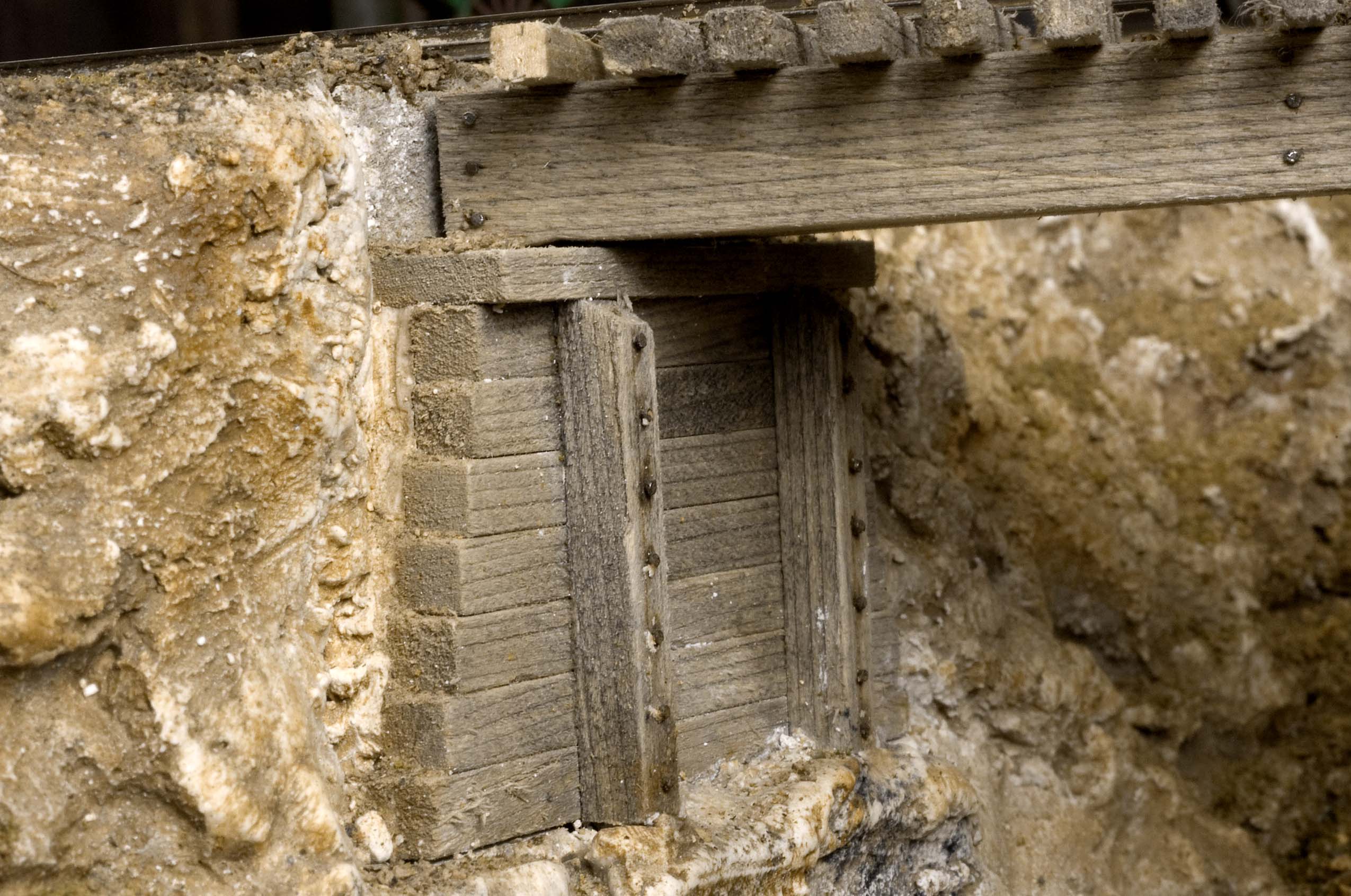 Photo 59 Heavy timbers make up the abutments for this short trestle that spans a shallow ravine in Tall Timbers. Short brads were used to secure the vertical timbers to the horizontal ones. |
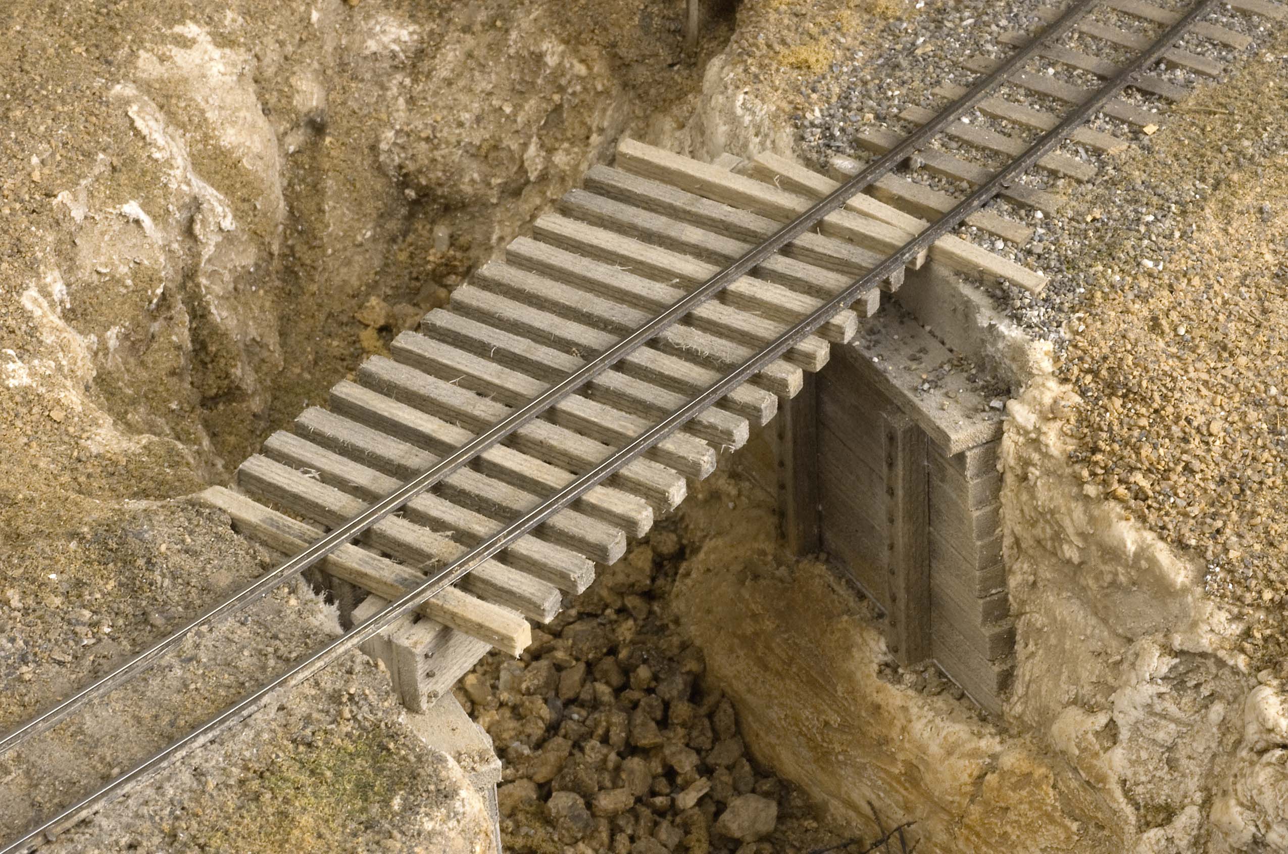 Photo 60 While all of the other bridges on the layout were made by removing the original rails and replacing them with a bridge, this little span was made with the rails remaining in place. The beams and crossties were slid in between the rails and the top of the abutments. | 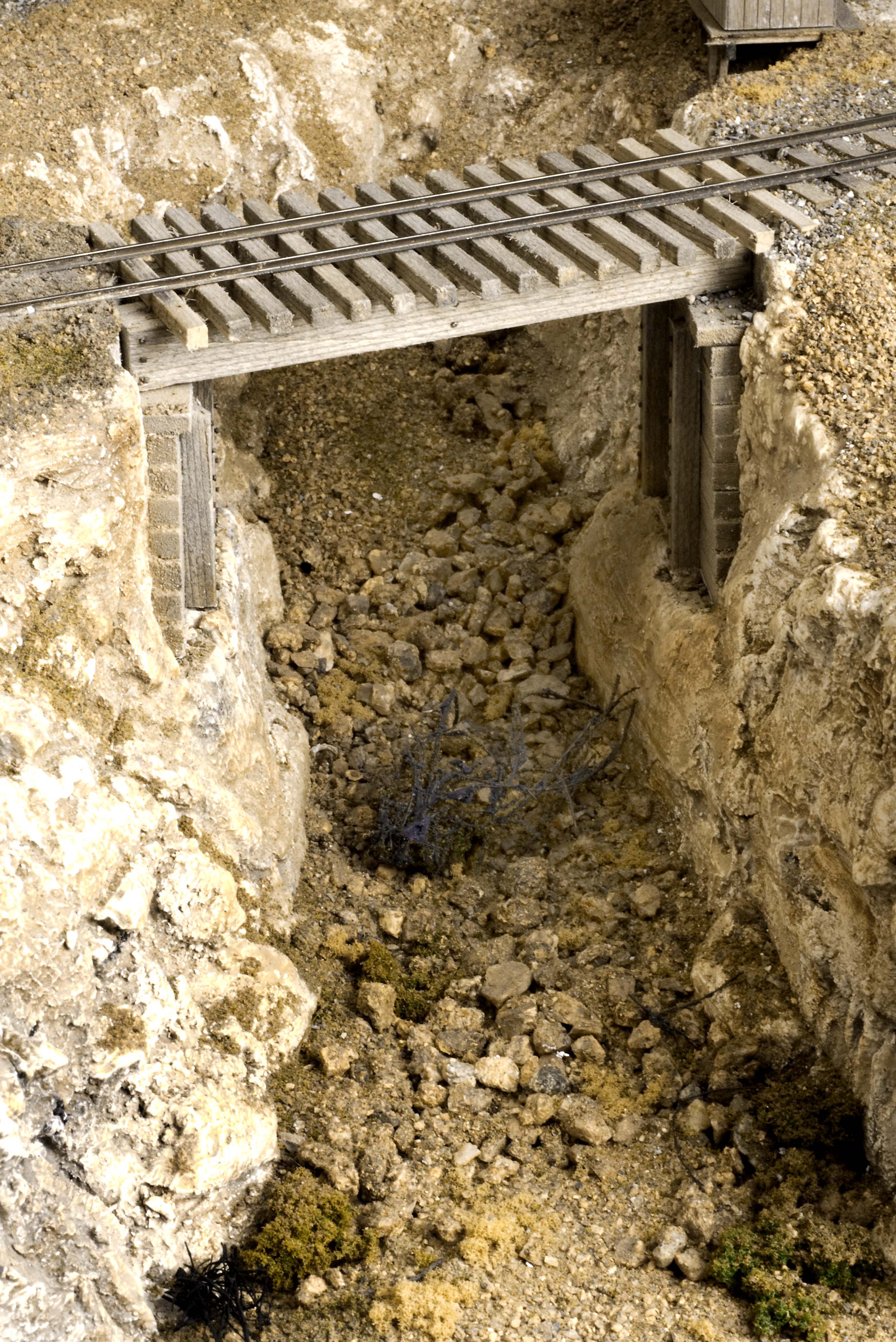 Photo 61 This little, "No Name," bridge is nothing more than a couple of large square beams resting on timber cribbing to create a short span to cross a shallow ravine. |
Click Here To Return To Railroad Home Page