

Welcome to my world of Sn3 Scale Model Railroading

Telluride Depot
By
Tom Troughton, MMR
| This document features my efforts at building the "S" Scale, Telluride Depot kit that was once produced by Banta Modelworks. Bill asked me to do a, "test build," of the model, then write and illustrate the instructions. | |
 Photo 1. The depot kit is typical of the other depots offered by Banta Modelworks in that it features an inner shell made of 1/16" thick aircraft plywood on which the modeler attaches the exterior components. The doors and windows are built up from "peel & stic" components and laser cut glazing. Metal chimney castings and laser cut shingles are used on the roof. |  Photo 2. Upon opening the kit and seeing all the many pieces of laser cut components, some modelers may become intimidated, but after spending a few minutes reading over the instructions and studying the photos, it's not that difficult of a project. |
 Photo 3. As with other depot kits, this one started by gluing the interior box components to the floor with yellow Elmer's glue. | 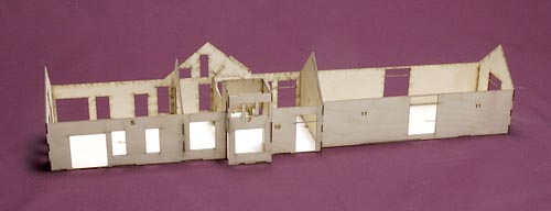 Photo 4. It took about an hour to complete the entire box. |
 Photo 5. Unlike prototype construction where building usually starts from the ground up, this one was built from the top of the walls down to the ground. It was easier to align and match the laser cut openings of the doors and windows in the clapboard exterior siding with those cut in the inner box. |  Photo 6. This structure utilized a couple of non-traditional adhesives for building models. Instead of spreading yellow glue over the exterior clapboard pieces, I employed some of 3-M's 465 Adhesive Transfer material. It's like double-face tape, which was also used in some areas, only it comes in rolls up to 24" wide. It's applied to the backside of the exterior piece and the excess it trimmed off. The protective backing is removed and it's positioned over its respective spot on the interior box, aligned and firmly pressed into place. |
 Photo 7. With the clapboard siding now in place, attach the few pieces of the flat, bass wood panels to the second floor areas and over the end wall sections. |
 Photo 8. The clapboard siding was then painted a depot buff color using a mix of liquid acrylic craft paints. While it was drying, the stripwood and wainscoting was painted a brown color with similar paints. A metal straight edge and razor blade were used to even up the bottom edge of the clapboard siding. It should end up being even with the lower edge of each window opening. |
 Photo 9. The cap rail was glued in place next, butting it up against the underside of the clapboard siding. It was extended completely across the window openings and just a short way into each door opening where it was sanded even with the opening with a sanding stick. All the corners were cut at 45 degree angles. | 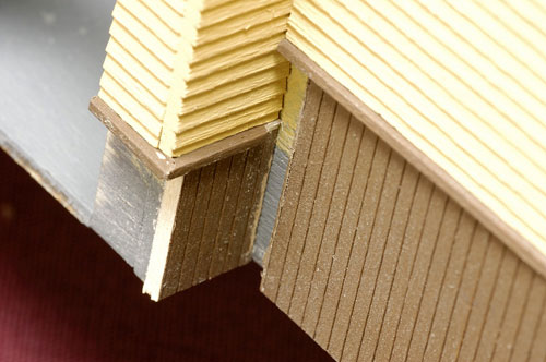 Photo 10. The wainscoting was attached next. In some cases, the cap rail needed to be notched in order for the wainscoting to form a clean edge with its mating edge. Let the material extend a bit beyond the ends of the building and at the regular door openings. The three doors of the baggage section required a special treatment. |
 Photo 11. The wainscot material was stopped even with the edges of the all three of the baggage section door openings. | 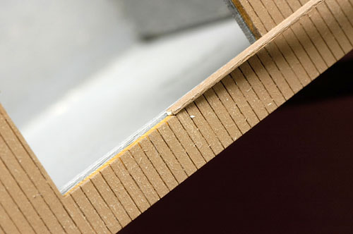 Photo 12. A shorter piece was cut and fitted in to fill in the space below the opening. It must be lower than the bottom edge of the door opening because a short piece of strip wood material will eventually be glued to the upper edge of the shorter piece, creating a threshold. |
 Photo 13. Because I opted to attach the exterior wall pieces from the top down, a small amount of material extended below the floor of the interior box. A model knife could be used to remove it, but I carefully attacked it with a belt sander that I mounted upside down to my work bench. Had the wainscoting been added first, this excess material would have definitely caused an alignment problem at virtually every window and door opening. | 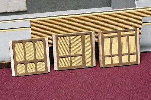 Photo 14. The components for the three large doors for the baggage section were brush painted and built-up next. The one on the left in this photo goes in the end wall of the baggage section while the other two are for the passenger end of the building. The one in the middle goes on the tower side of the building while the door on the right goes on the bay window side. |
 Photo 15. All of the doors require short pieces of stripwood to hide the edge of the siding material. Measure the pieces and glue them in place against each door. |  Photo 16. The "peel & stic" outer frame goes on next. To determine how much of the cap rail needs to be removed, hold the frame upside down and centered on each door and carefully make marks with a knife, then remove the material. |
 Photo 17. With the offending material out of the way, peel off the protective backing from the rear of the frame and press it into place. Tiny dots of Lightning Bond CA adhesive were used throughout this building project to reinforce all the "peel & stic" bonds. | 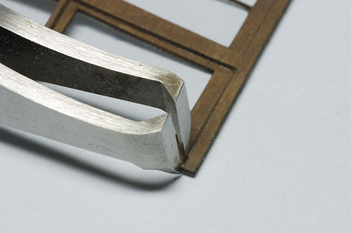 Photo 18. The windows are extremely fragile and must be assembled carefully. The were made up in a batch and separated into plastic bags accordingly to their respective wall location. There's a tiny amount of material spanning the lower edge of each frame. Leave it on until the window is completed, then clip if off with a nipper, such as those sold by PBL. |
 Photo 19. Some of the window frames were integrated with building trim, so the insertion of them was left for a later time. Those that had their own frames were mounted in place with their "peel & stic" adhesive and reinforced with the CA adhesive. | 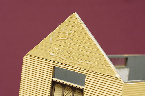 Photo 20. The flat, laser-scribed pieces of bass wood above the clapboard in a few locations need to be covered with the paper shingle material. In the past, I've attached these with white glue, but it's been a time consuming process. The vertical shake siding on this building was attached with a product called "Scatter-Grip" which was painted on with a soft brush. It's a water based, milky white product that dries to an extremely sticky adhesive. The bass wood was first sealed with sanding sealer, allowed to dry then lightly sanded to a smooth surface. Two coats of the "Scatter-Grip" were applied and allowed to dry. |
 Photo 21. The laser-cut shake shingle strips were applied a course at a time with each course being burnished into place with the flat end of a model knife blade holder. When dry, the excess was trimmed off with a sharp blade. A bead of CA adhesive was applied to the edge of the rows to reinforce their bond. |  Photo 22. The shakes were painted the same buff color as the clapboard siding, and when dry, the laser-cut trim piece was attached using it's "peel & stic" material. |
 Photo 23. The second floor walls received the shake siding too, but because of the special curved platform roof in this area, it started even with the lower edge of the window opening. |  Photo 24. The siding shakes were painted and when dry, the sills, windows and frames were attached. |
 Photo 25. Before proceeding further, the tower side roof section of the baggage section was secured in place and covered with the shake shingle material. Once again, the "Scatter-Grip" adhesive was brushed in place and used to attach the shake shingles. They were painted their Polly Scale "Grimy Black" color about an inch out from the mating station wall because it would be difficult to paint them with that roof in place. |  Photo 26. All the roof panels were test fitted and taped in place. The chimney openings were enlarged to accept the metal castings. The two short chimneys go on the ridge line locations and the taller one goes in the opening on the longest roof panel. |
 Photo 27. The chimney support brackets were assembled and attached to the under side of the roof panels. They were positioned to provide as much of a shelf as possible to support the metal castings. | 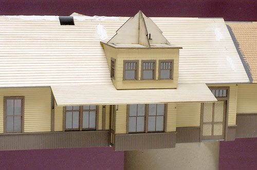 Photo 28. The station roof for the tower side must be attached first, because of the locations of the chimney supporting shelves. It's glued in place into the grooves of the tower and onto the tabs of the end and interior supporting walls. |
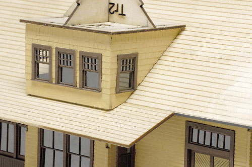 Photo 29. The small platform roof was test fitted next, but not glued in place yet. It should form a tight seam with the larger roof. If not, remove some material from the "tower notch" with a sanding stick until it fits tight up against the other roof panel. |  Photo 30. Once the platform roof appears to fit, attach the corbel supports to the face of the clapboard siding and then the corbels themselves. |
 Photo 31. Besides the three large ones that mount on the main wall, there's three that attach to the tower also. The platform roof was temporarily set back in place, just long enough to determine the length of the short filler piece of stripwood that needs to be attached above the center mullion of the window. |
 Photo 32. The platform roof was glued to the already mounted corbels and when it was secured, the center corbel was attached to the short piece of stripwood and the underside of the roof. A small amount of the tip of the three short corbels had to be sanded of flush with the lower edge of the roof panel. |
 Photo 33. The long roof panel was attached next, however before adding the two roof pieces over the bay window area, the windows needed some extra special treatment. Most of the windows or door in this "test build" model didn't receive any shade or curtain treatments, but the two windows in this short second floor area needed something to block the view of the roof that was less than an inch away. Small pieces of a fine cloth were glued in place to represent curtains, hiding the view of the roof. |  Photo 34. With those curtains in place, the two pieces of the roof were glued together, then onto the long roof piece. The short roof over the bay window protrusion went on last. |
 Photo 35. Squadron putty was used throughout the construction of this model to fill in any gaps between roof panels and any depressions that may have existed at their tab and slot locations. When it had hardened, it was sanded smooth with a sanding stick. |  Photo 36. The corbel supports and their respective corbels were secured to their locations on the bay window side of the building. There's an odd one that doesn't have an angle along its top edge. It goes in the extreme left hole. |
 Photo 37. The "L" shaped platform roof needed a little bit of carving and sanding off its upper end before it fit tight against the long roof. When shaped properly, it was glued in place. This roof was covered with roll roofing material rather than cedar shakes. Silk span tissue was cut to 3' widths and secured in place with Polly Scale "Tarnished Black" paint. With this roof in place, the shake shingles for the long roof were attached with "Scatter-Grip" with their edges and valleys reinforced with CA adhesive. |  Photo 38. The short platform roof on the tower side needed additional work before it was ready for the shake shingles. It has a curved or rolled-up surface that extends up to the underside of the window sills. A laser-cut piece of index card type material curled by rolling it around the handle of my Xacto knife, then glued in place with yellow Elmer's glue. |
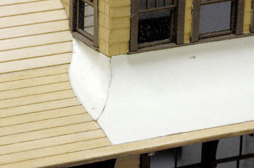 Photo 39. The two small side pieces of the rolled roof needed to be re-cut. Eventually two pieces were created that fit into place. | 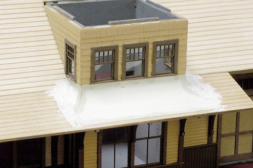 Photo 40. Once again, Squadron putty was liberally applied along the edges of the paper rolled roof portion and when dried, sanded to create a smooth transition for the shingles. |
 Photo 41. Sanding sealer was carefully brushed onto the platform and rolled roof portions. When dry, two applications of "Scatter-Grip" were brushed on to hold the shake shingles. | 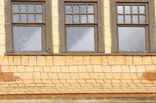 Photo 42. The shingles were lined up with the laser-scribed lines and fitted into place along the curved portions of the rolled roof. A bead of Lightning Bond was applied along the edges of the shingles to reinforce the bond. The area below the window sill was shingled with single pieces of the shingle material, held in place with white Elmer's glue. |
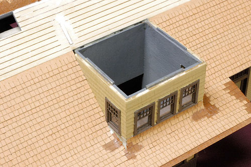 Photo 43. The shingles were applied in courses up to the top edge of the tower, but no higher. |  Photo 44. The shakes next to the tower wall were painted about an inch because it would be difficult to reach them once the tower roof was in place. |
 Photo 45. The interior support for the tower roof was assembled and temporarily set in place. The rear triangular element of the tower roof was glued to it's holding edge, BUT NOT the roof, because it would need to be removed for the preceding steps. |  Photo 46. The three remaining roof pieces were glued to the frame and held in place with tape and weights. The roof is still temporarily resting in place. |
 Photo 47. When the glue joints were solid, the roof piece was removed and the edges filled with Squadron putty. The finished edges needed more work, so Durham's Water Putty was mixed up with a small amount of yellow Elmer's glue and liberally applied along all the four seams. It was temporarily set in place on the tower once again while the putty hardened. | 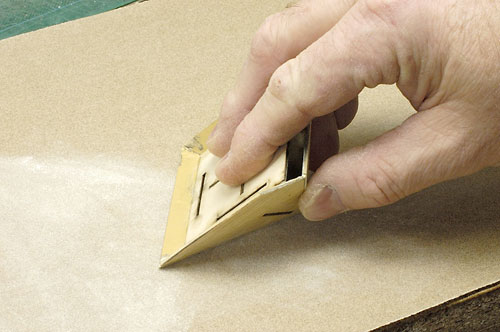 Photo 48. The roof was removed and the putty sanded to a hard edge with the sand paper sitting on the hard surface of my shop table saw. |
 Photo 49. With it's edges sanded and sealed with sanding sealer, the tower roof was finally glued in place. |  Photo 50. Additional Squadron putty was forced into the gaps that were between the tower roof and the main roof. When dry, the excess was carved away and sanded smooth. |
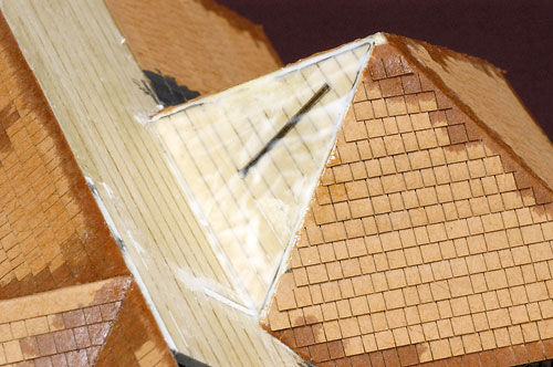 Photo 51. The tower roof was painted with "Scatter-Grip" and the shake shingles were worked into place. | 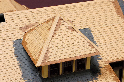 Photo 52. The main roof was shingles up to it's peak. The seams along the panels of the tower roof were finished with 1/4" wide strips of the shingle carrier sheet. |
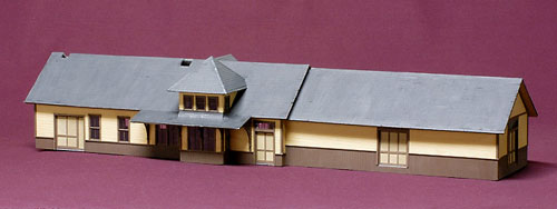 Photo 53. The roof was completely painted with Polly Scale "Grimy Black". |  Photo 54. he three metal chimney castings were primed with Krylon Gray Primer, then brush painted with the same depot buff and brown colors used on the walls. |
 Photo 55. After the holes were checked to make sure the castings could be aligned vertically, a tiny amount of 5-Minute Epoxy was applied to the bottom and inserted into the proper hole. It was checked often to make sure that it remained vertical until the bond had set. |  Photo 56. When the castings were firmly in place, additional epoxy was placed in the seam between the bricks and the shake shingles. A dental pic was used to carefully place the adhesive. |
 Photo 57. The epoxy "fillet" was painted a glossy black color to represent roofing tar that was applied to prevent water from leaking into the building. | 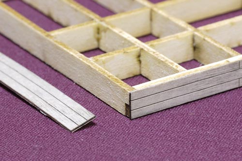 Photo 58. The supporting framework for the loading platform was assembled using a small metal square to keep everything at right angle to one another. |
 Photo 59. The scribed decking and the facing for the platform were stained with a black shoe dye and alcohol solution. When dry, the protective covering for the facing was removed and the three pieces were attached with their "peel and stic" adhesive to the outer edges of the platform framework. The completed framework was then glued to the building, making sure that its lower edge was even with the base of the structure. |  Photo 60. The small amount of wainscoting that was below each of the baggage section doors would interfere with the platform decking. |
 Photo 61. The excess material was removed with a sharp #11 Xacto blade. The area will eventually be filled with a piece of strip wood. |  Photo 62. Before attaching the decking, it was test fitted in place to make sure that the vertical pieces of the door frame didn't cause interference. A small amount of material was removed to allow the decking to fit tightly against the building. |
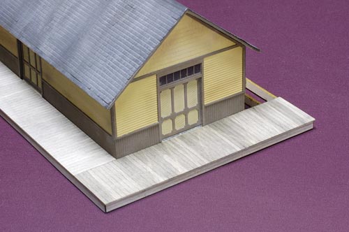 Photo 63. The end piece of the decking was aligned on the framework at the end of the building and glued in place with yellow glue. When dry, the remaining decking for the sides and ramps was attached to the rest of the framework. | 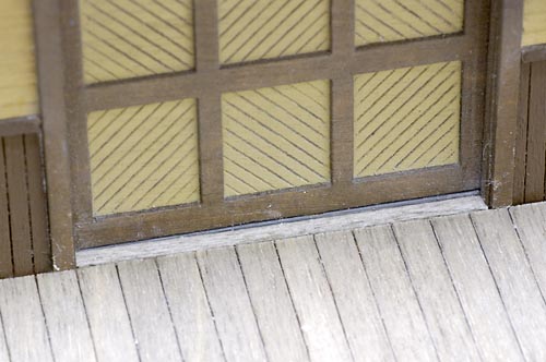 Photo 64. A short length of 2x4 strip wood was stained and glued into the area between the decking and doors to represent a threshold. |
 Photo 65. Here's a finished view of the bay window side of the building. It's been weathered with powered pastel artist chalks and white powder from a home improvement dry wall project. |  Photo 66. This is the tower side of the depot. All that remains is to set it in place along the tracks and add some station details and waiting passengers. |
 Photo 67. Here's a view of the baggage end of the building. | 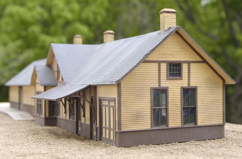 Photo 68. The final image in the document is of the station end of the depot. |