

Welcome to my world of Sn3 Scale Model Railroading

Moving The Points
By
Tom Troughton, MMR
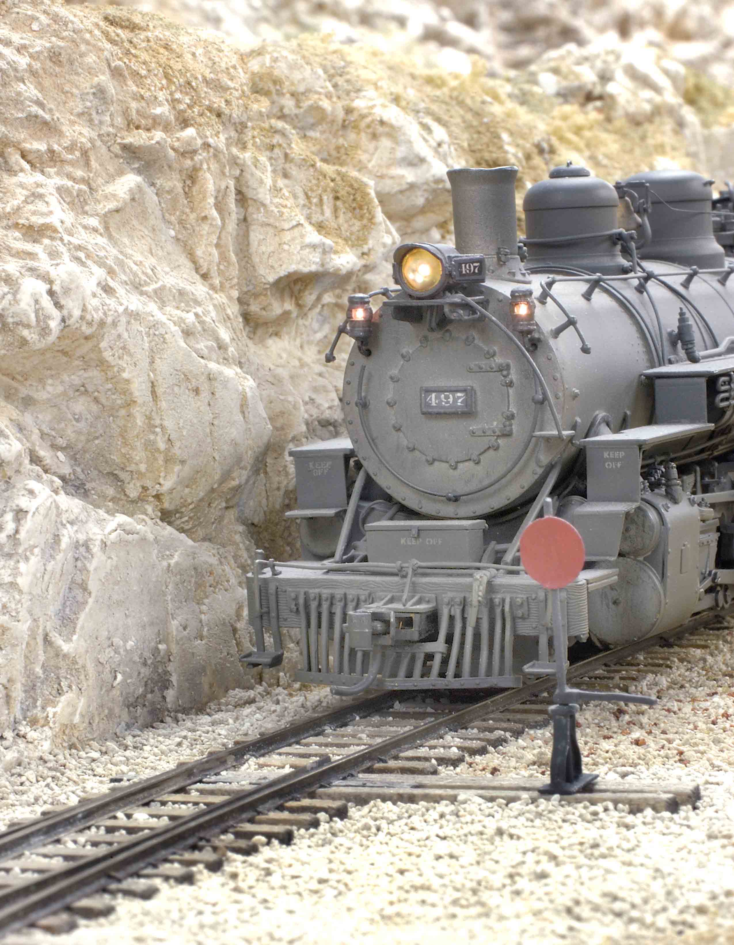 This document is similar to one that appeared in the February 2008 issue of, "Scale Rails," which was the name of the monthy publication issued by the NMRA. Many of the photos used in that article appear here also, but the text has been edited to fit this format better. Over the past four decades, I've probably built and hand-laid over a hundred or so turnouts. I know in the prototype world they're called, "switches," but for this article, I'm going to stick with the common modelers usage of the term, "turnout." My first efforts at handlaying track and turnouts consisted of removing the rail from its fiber or plastic ties, then spiking the pieces back onto hand-laid wooden ties. I didn't have to do any frog and point filing back then, but at least I was learning how to lay track. I had just completed a short spur to a small community on my Sn3 Cimarron and Tall Timbers RR and needed to add another switch. While I'm not going to describe the complete hand-laying details of the turnout, I do plan to illustrate how I actually connect and move the points of this new turnout. | |
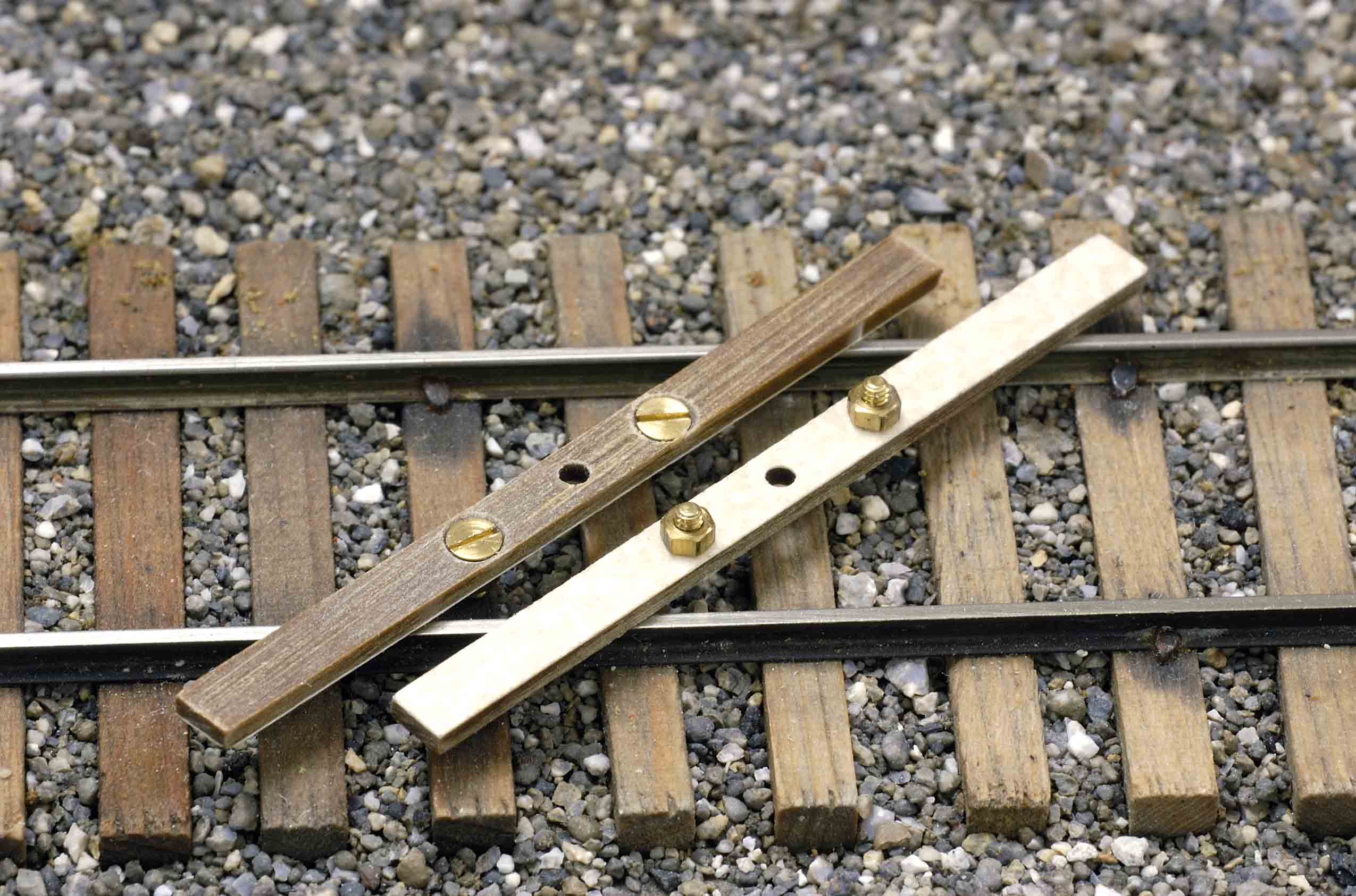 All the points on the other turnouts on my layout are soldered to the flat head of an 0-80 brass machine screw. The throw bars were made from thin strips of Formica with the underside facing upward. After measuring, locating and drilling holes for the screws, the upper side of the holes were slightly counter sunk to allow the head of the tiny brass screw to sit flush with the surface of the tie. Brass 0-80 nuts were attached to the threads that extended below the throwbar, then tightened to the bottom of the tie. It was loosened to allow the screw to rotate in the hole. When I was happy with the fit, a dot of CA adhesive to the bottom of the nut to secure it to the screw, securing it in place but still allowing the screw to rotate in the hole. | 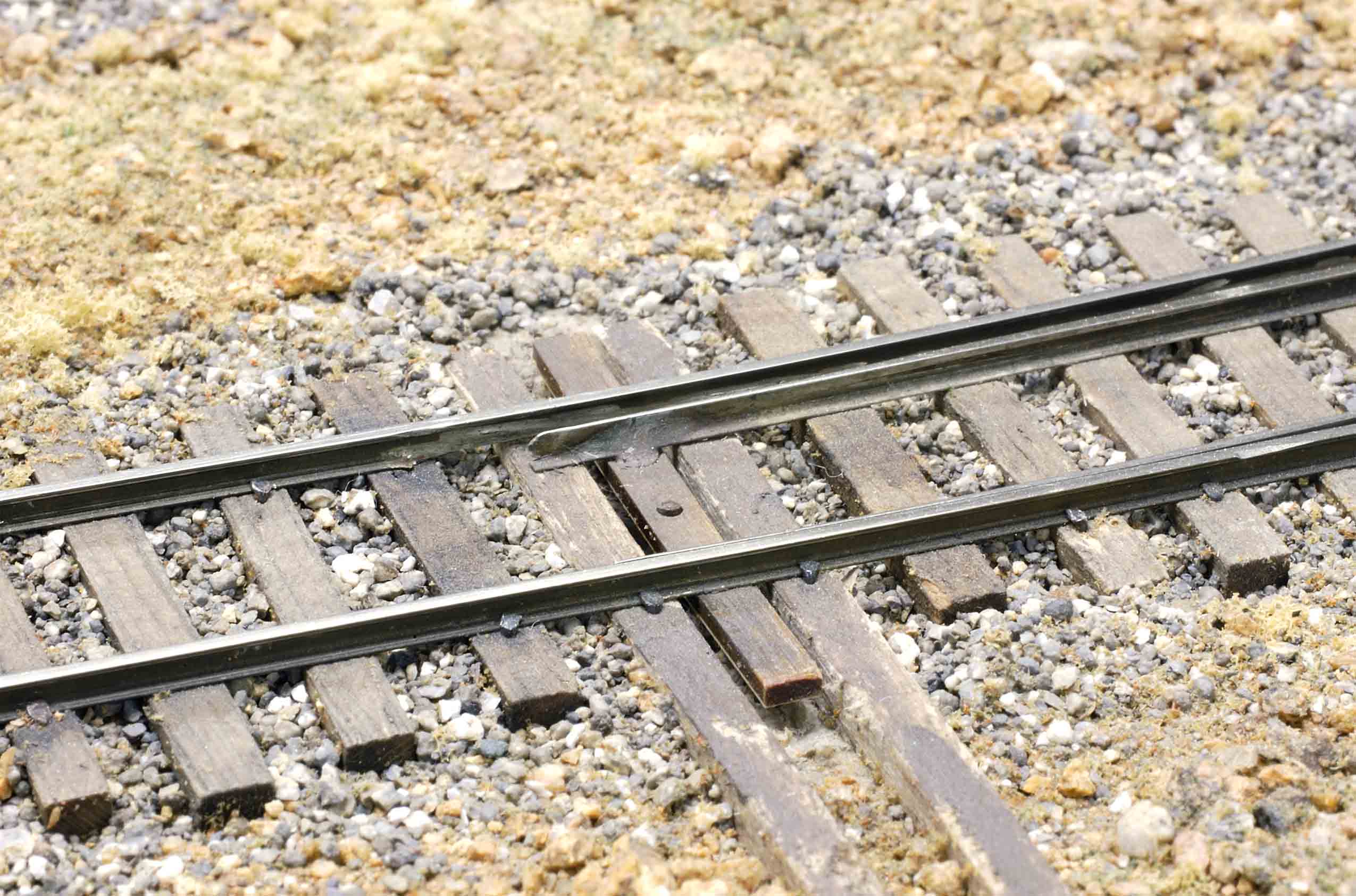 The bottom surface of the point rails were then soldered to the top of the flat head screw. When the points moved back and forth, the tiny screws rotated. Prior to building turnouts with the small screws, I used to solder the points directly to PC ties. However, over time and usage, the solder joints failed. |
| That was a lot of work and I was never happy working with the Formica, mainly because it tended to melt when soldering the rail to the head of the screw. I wanted to try something different with this last turnout. Steve Hatch, owner of Railway Engineering, (www.railwayeng.com) builds turnouts for model railroaders for a living. He and I were emailing one another about how to attach the points to throw bars and I mentioned using simple straight pins. He said that he used brass plated dress maker pins to connect the stub rails of his stub turnouts. I thought I'd give his method a try with this new turnout. | |
 I first tried to see if I could get solder to bond to an ordinary steel straight pin but wasn't very successful, even after coating it with a lot of flux. They were the common silver looking pins that are used to hold men's shirt together when they are on the display racks. I then tried making my own pins out of brass wire, but I failed miserably when I tried mashing one of the ends down to form a flat head. I had better luck cruising the jewelry making aisle at our local, "Hobby Lobby," store when I came across a package of one inch long, single headed brass colored pins packaged by, "The Jewelry Shoppe Findings," ( www.craftetc.com ). The price was 36 pins for a dollar which seemed right to me. However, before taking them home, I checked them with a magnet that I found in another aisle to determine if they were steel and would probably act just like the other pins I had at home. The brass looking pins weren't affected by the magnet, so home they went where I tested one and found it accepted solder. | 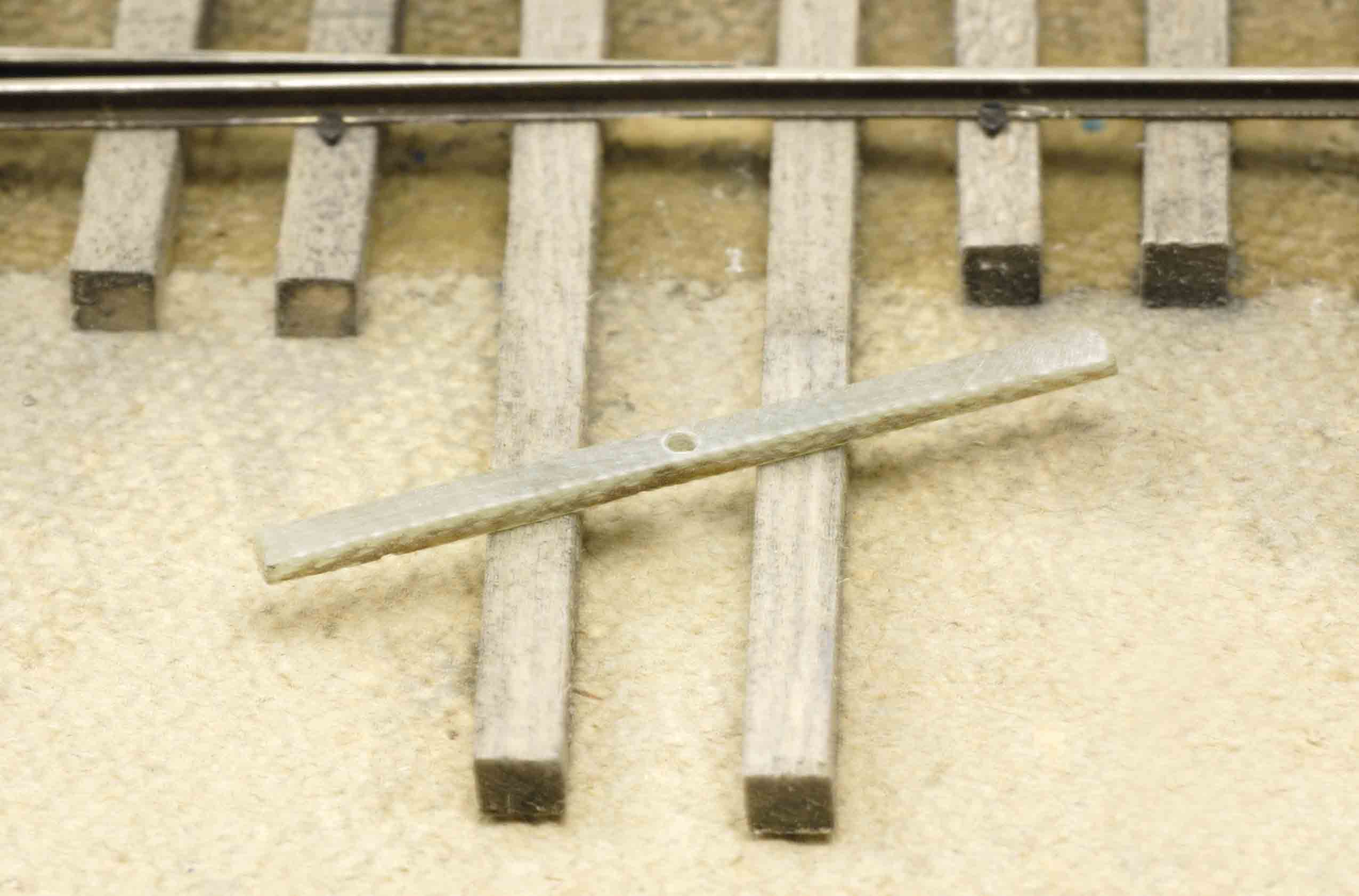 My next step was to make the actual throw bar from a short length of, "Clover House," (www.cloverhouse.com) throw bar material. It's a thin strip of double sided printed circuit board. The copper plated surfaces were rubbed on a sheet of 150 grit sand paper to remove the plating, leaving the bare fiberglass material behind. I knew I could have simply cut a couple of gaps in the bottom side plating but I wanted to remove it just to be safe. I tried removing the copper plating with Radio Shack's, "Archer's Etchant," but it took longer than the sanding, but I'm sure that method would eventually have worked. After measuring and cutting it to length, I drilled a hole in its center for the actuating wire from a Tortoise switch machine. I've discovered that the wire that is packaged with the Tortoise machines wasn't strong enough to move the throw bars on my turnouts so I use .047" music wire instead. I also used the #55 drill, which is .052" in diameter, to enlarge the respective factory drilled holes in the Tortoise housing. | 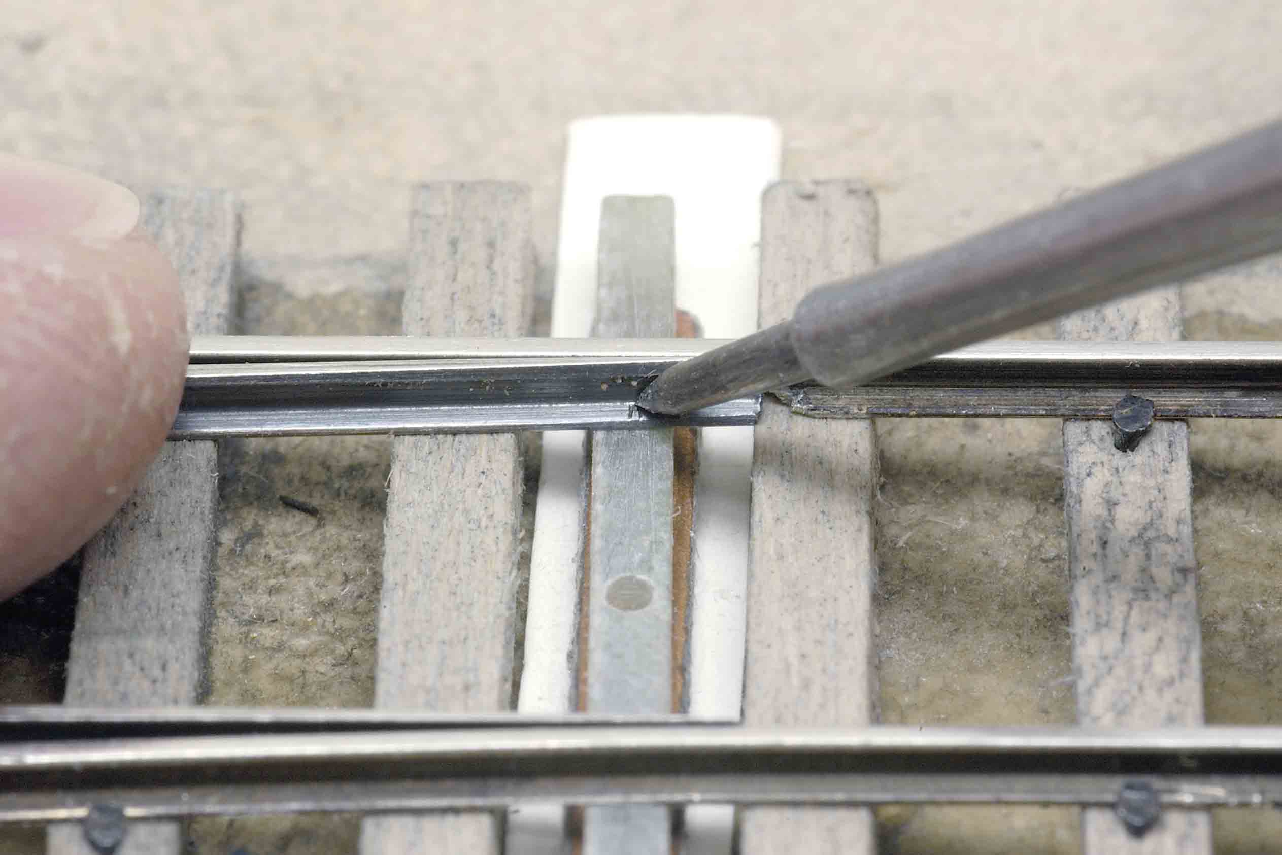 With the actuating hole drilled, the two point rails were temporarily spiked back in place. The throw bar was wedged in with shims under the. A needle scribe was used to mark the point rails where they met the throw bar. They were removed once again so that tiny notches could be filed into their flange. These notches would be the locations of the brass pins. | 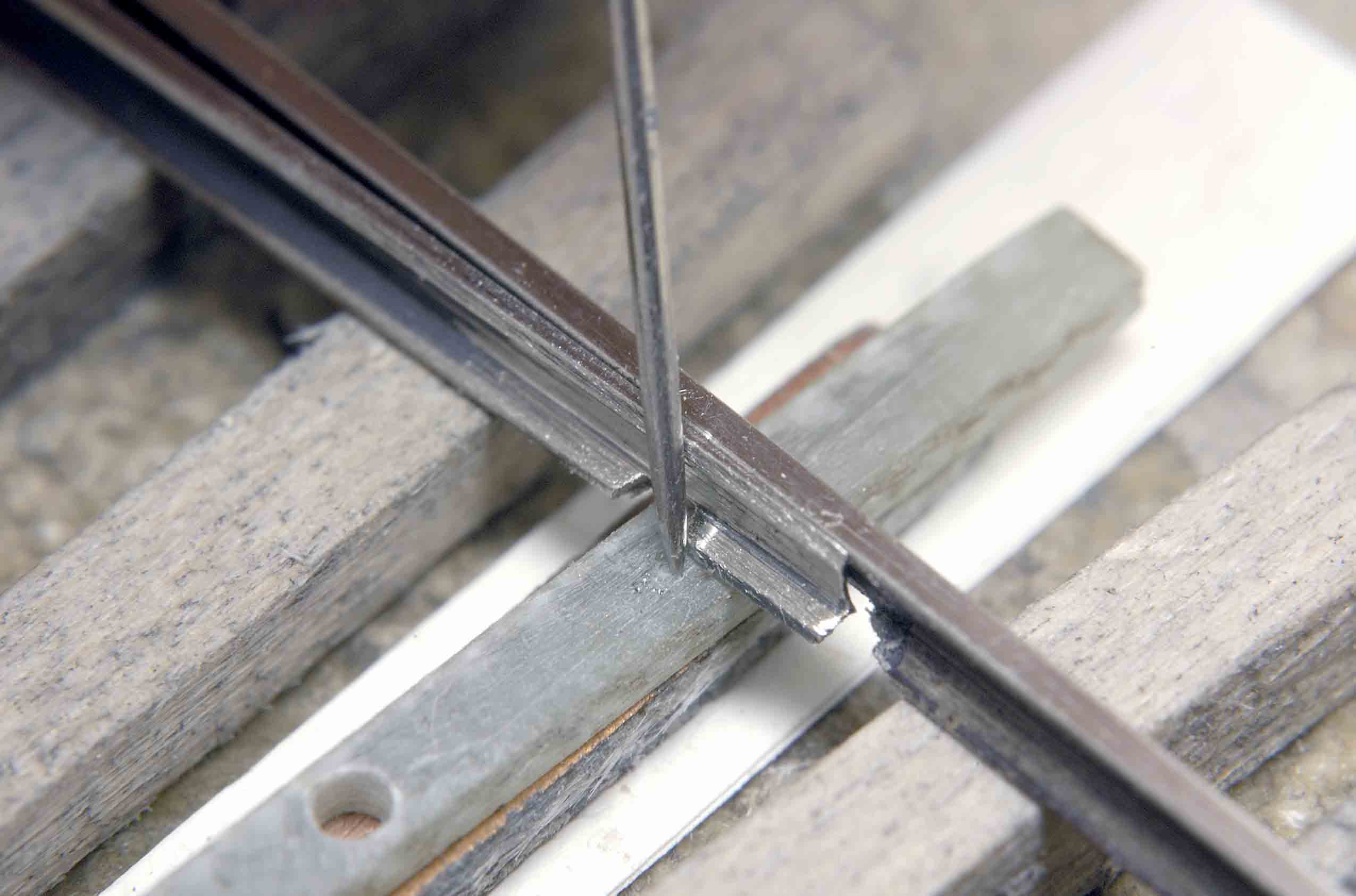 The notched point rails were slid back in the turnout and the throw bar was wedged in place with the notches in the points centered on it. I used the NMRA Sn3 track gauge to determine the proper gap between the point and stock rail, then a sharp needle was used to put a tiny, "dent," in the throw bar. |
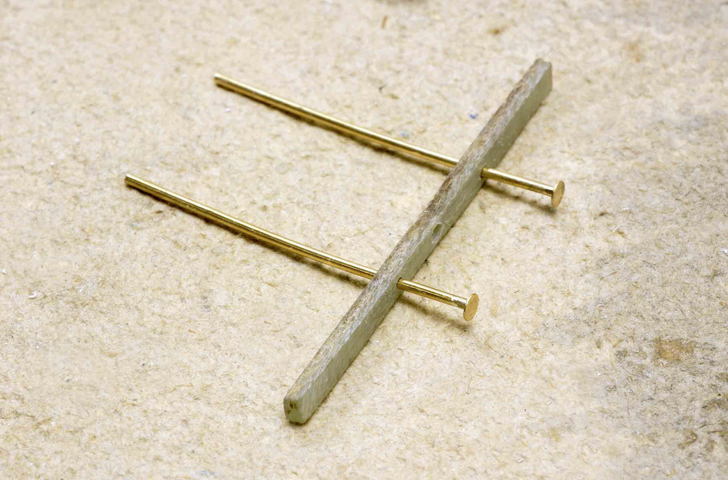 The throw bar was removed one more time and clearance holes were drilled for the brass pins. I wanted them to be able to rotate in the throw bar. I used a #69 drill, which is a bit larger than the .023" diameter of the brass pins. Because the copper plating was removed from the underside of the throw bar, I didn't have to worry about the heads of the pins causing any electrical shorts. | 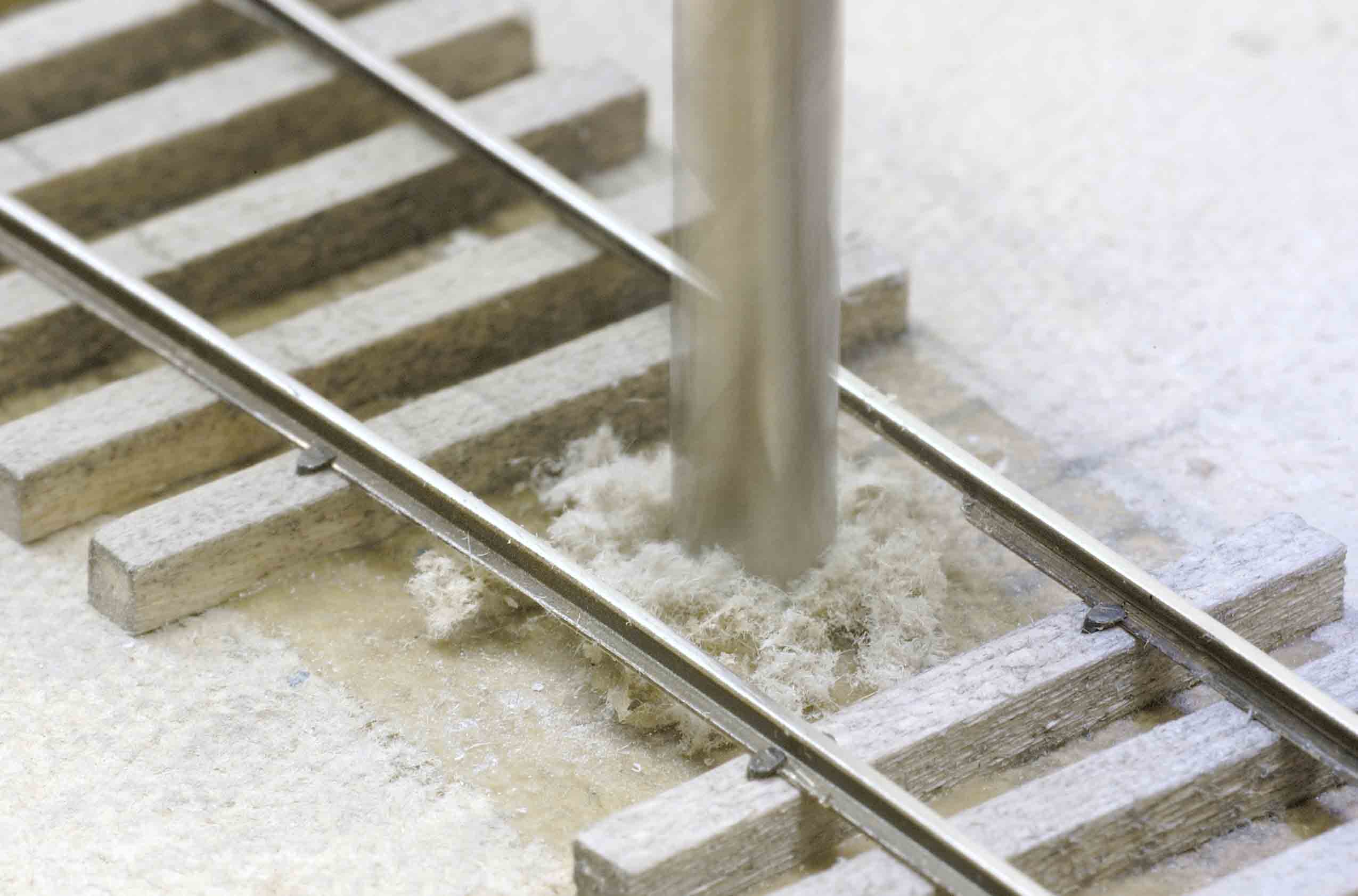 The throw bar was again set in its proper location. A 55 drill was pushed through the drilled hole for the actuating wire to make a mark in the Homasote. Since the two point rails were still out of the way, a 1/4" hole was drilled through the Homasote and 5/8" Industrial Particle Board sub-roadbed at the marked site. I increased the size of the hole through the particle board from below with a slightly larger drill, being careful not to go into the Homasote because I wanted the larger diameter to eliminate any chance that the throw bar actuating wire might hit the wood. |
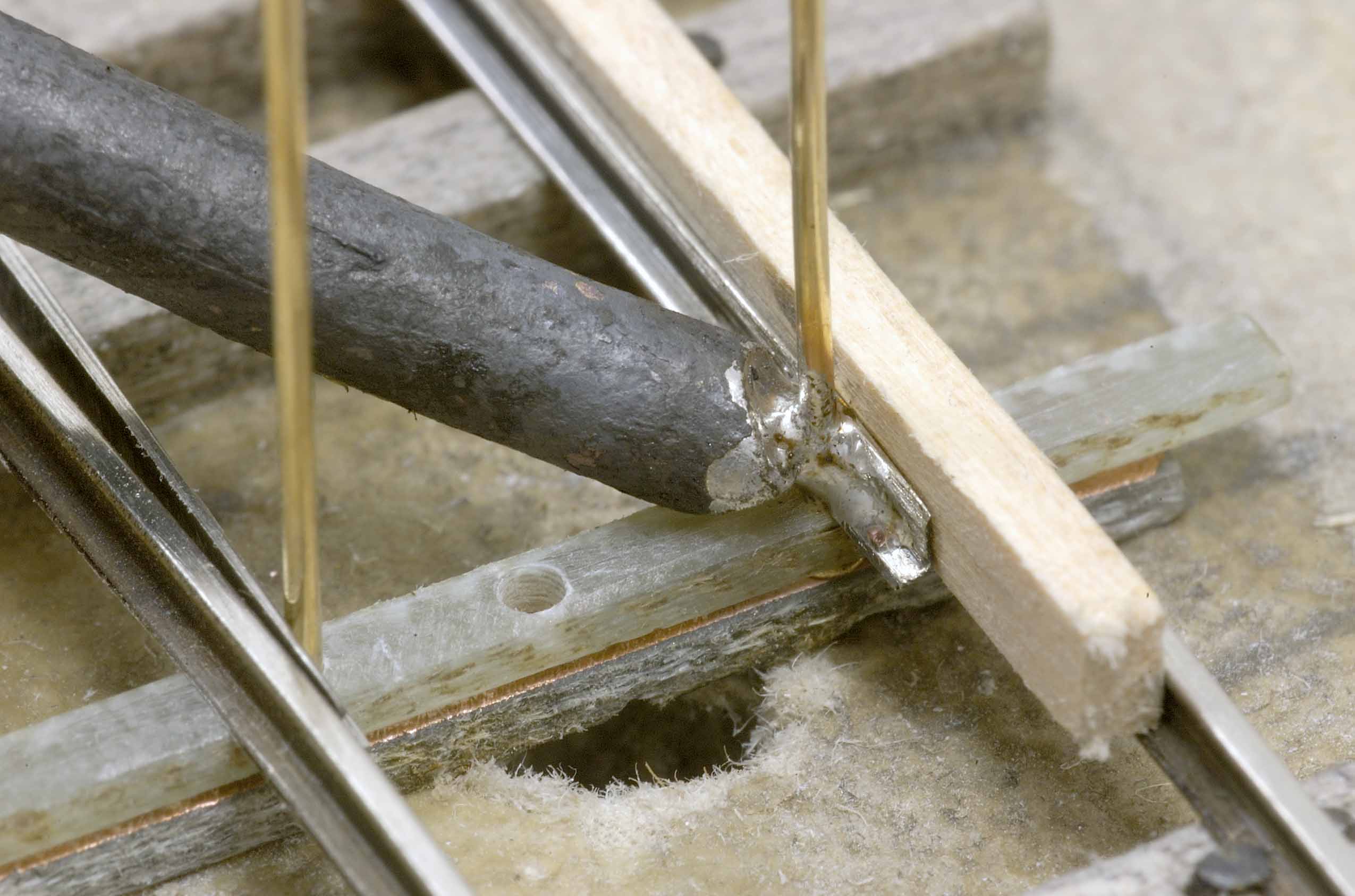 The two pins were placed in the throw bar and carefully worked and turned up into position. It was awkward and took some gentle bending, but I finally got it into place. The throw bar was lined up and the end of the point rails were re-spiked and soldered for the final time to their printed circuit ties near the frog. Another PC tie was temporarily wedged into place below the throw bar to raise it into position so that the pins were now resting in their respective notches with their heads firmly held tight against its underside. A small piece of wood, equal to the point gap distance, was set in place between the stock rails and points to keep their metal faces separated while the pins were soldered into the filed gaps with a 25 watt soldering iron. | 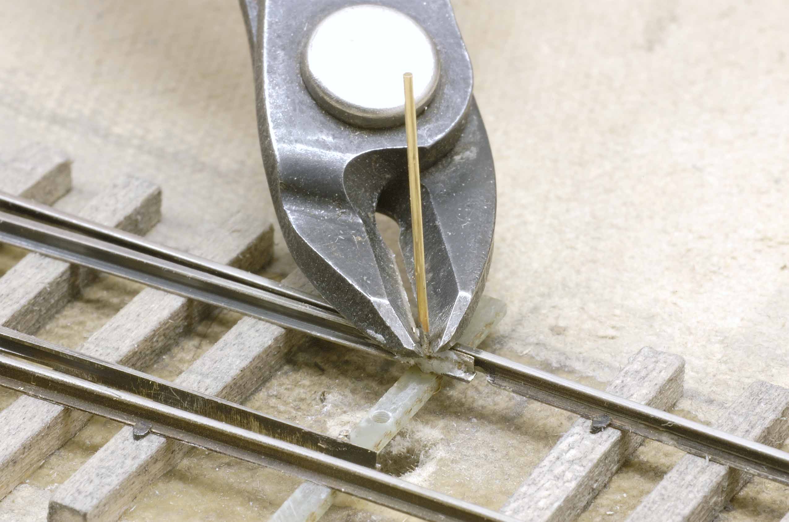 Wearing eye protection, the excess length of pin material extending above the rail head was trimmed away with a pair of flush cutting nippers the points and throw bar moved a bit to assure that the pins were free, allowing them to rotate without putting any strain on the solder joints. |
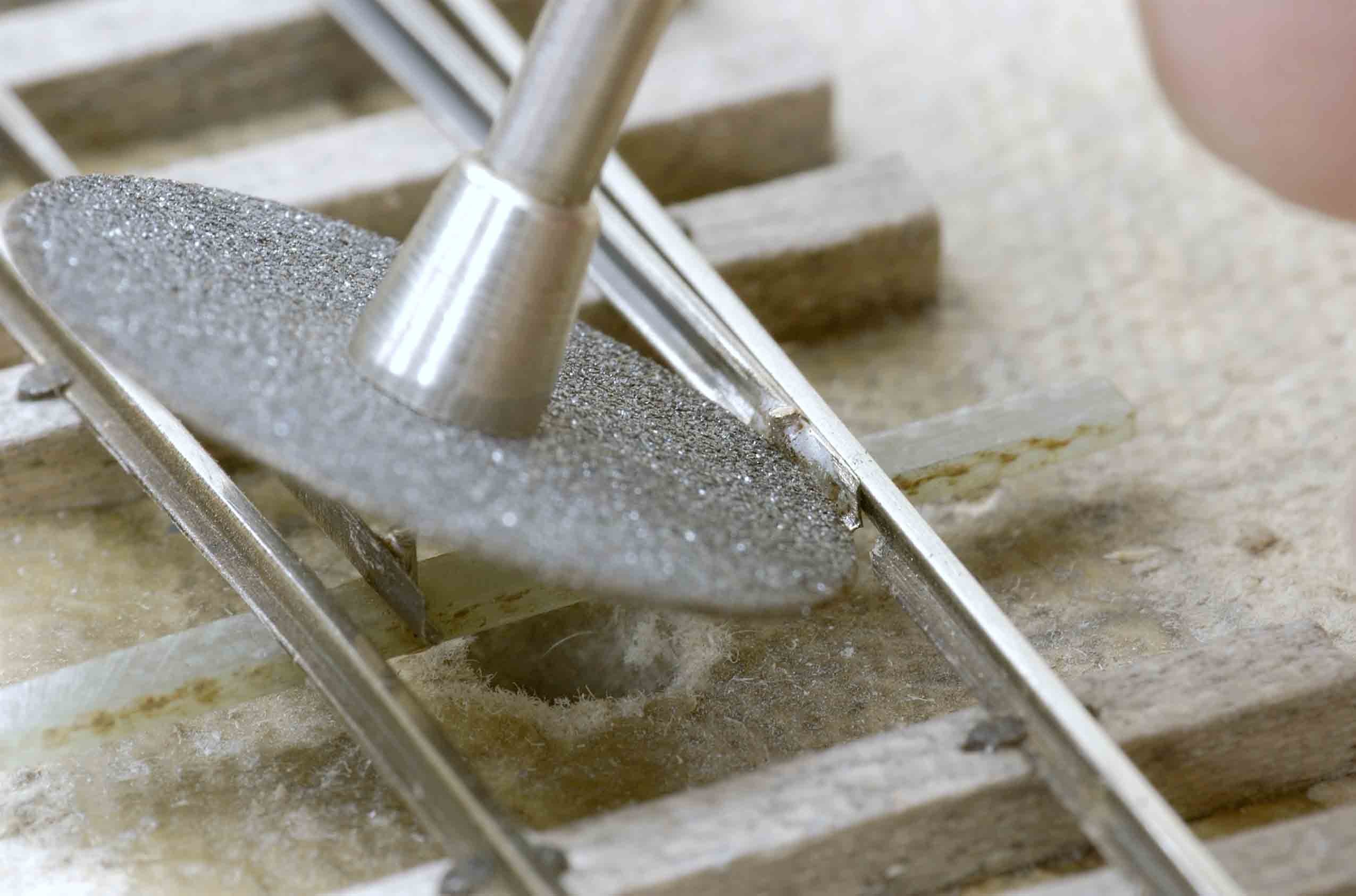 A cut-off disk and a Dremel tool made it easy to quickly dress up the solder joint on the inside of the point rail. I had to be extremely careful to not remove too much material because I could have ground off the short nub of the brass pin touching the rail. | 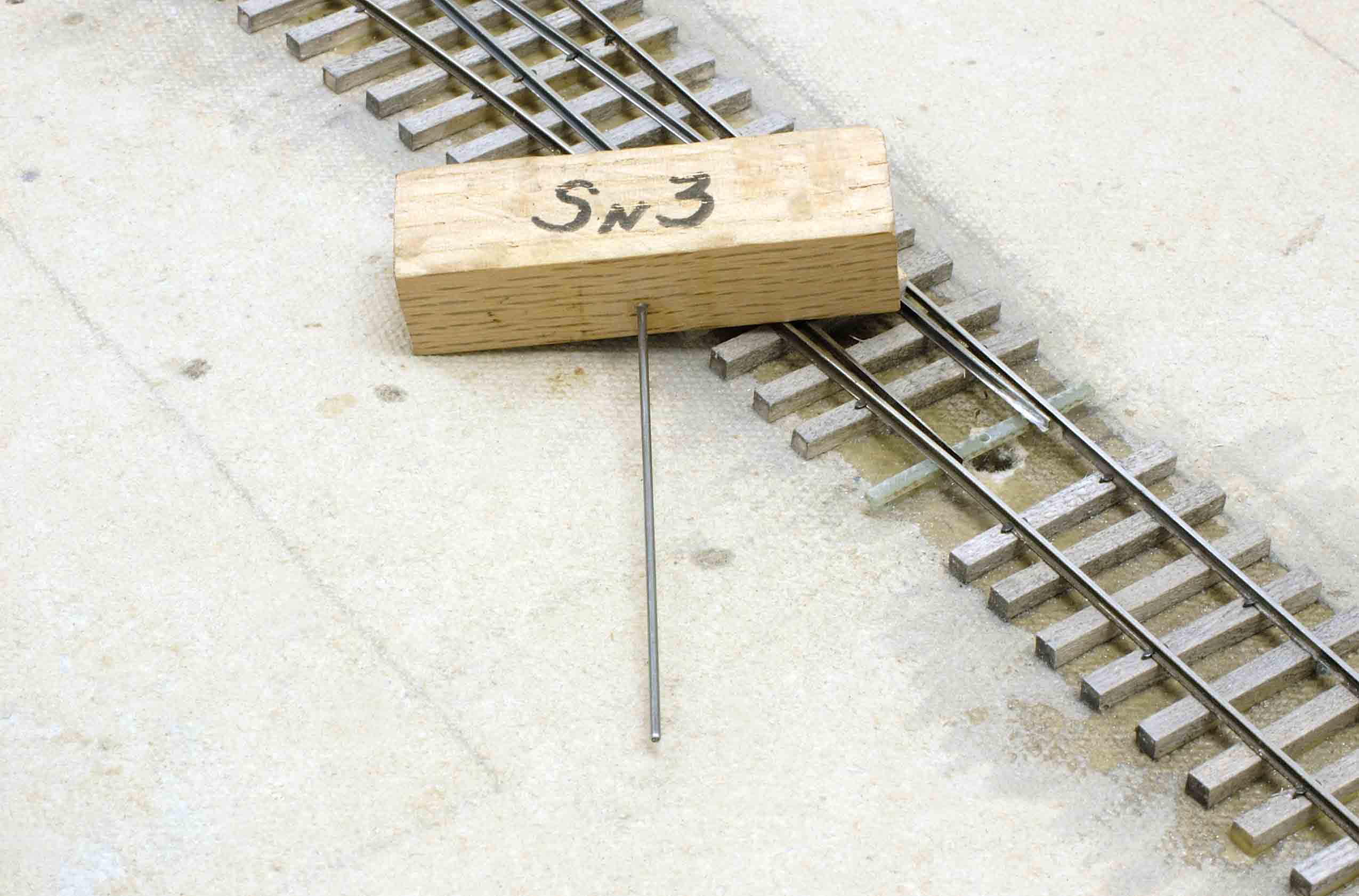 Tortoise switch machines are used to throw all my turnouts. To help aid in locating their actuating wire, I use a simple wood and wire jig I made from the same actuating wire material that's used on the Tortoise. It's simply placed through the hole in the throw bar. To keep it in place when I'm working under the layout, I'll set a real railroad spike on the wooden block to keep it from moving. |
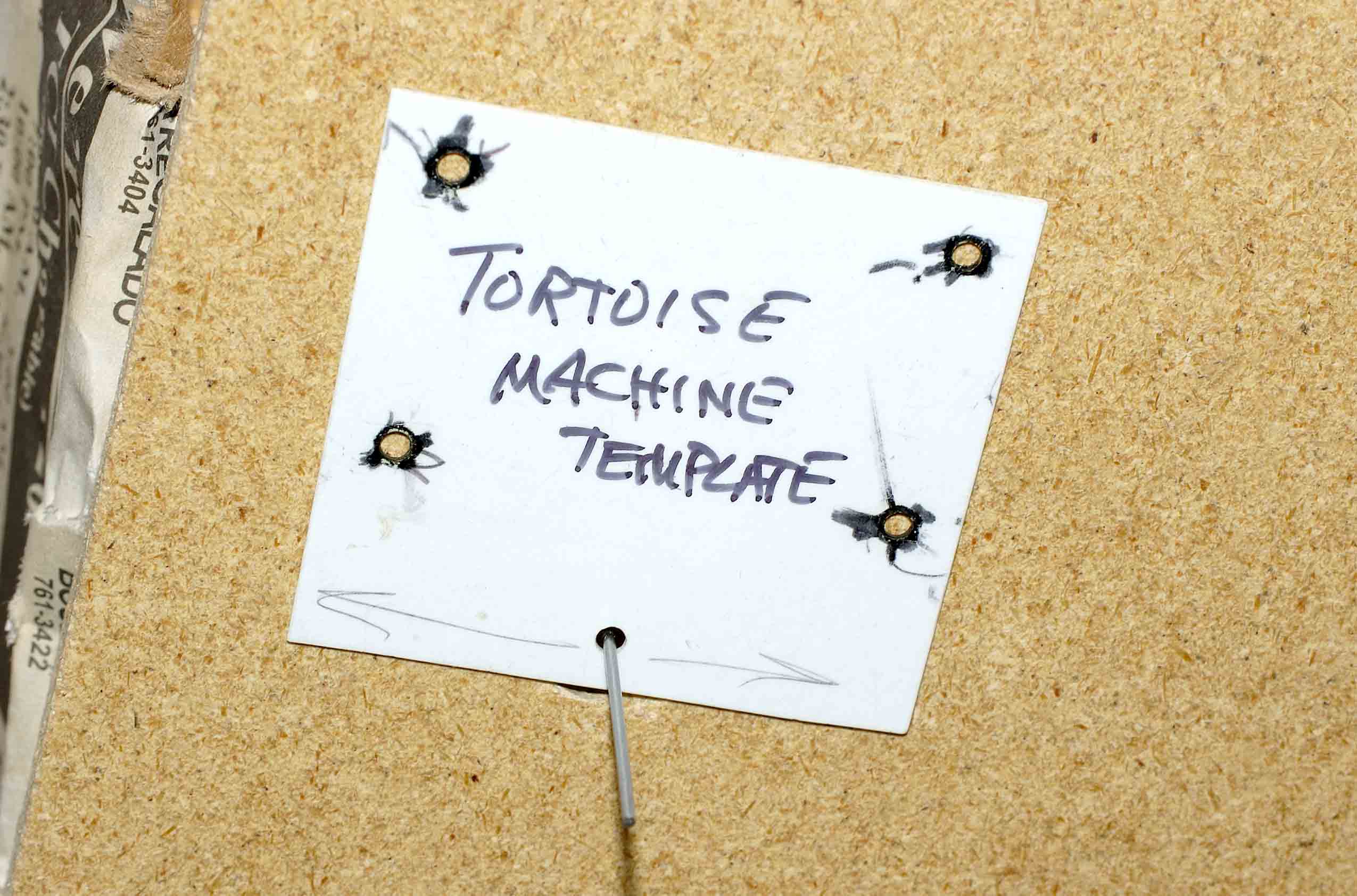 To position the Tortoise correctly, a styrene drilling template that's based on the diagram included on the instruction sheet is used. After installing more than 50 Tortoise machines over the years, I finally figured out how to make the process easier which simply involves dabbing a small amount of Aleene's Tacky Glue on the styrene and pressing it in place against the underside of the particle board. With the fwire from the throw bar lever jig centered in its appropriate hole, a Sharpie marker pen was used to mark the locations for the four mounting screws. | 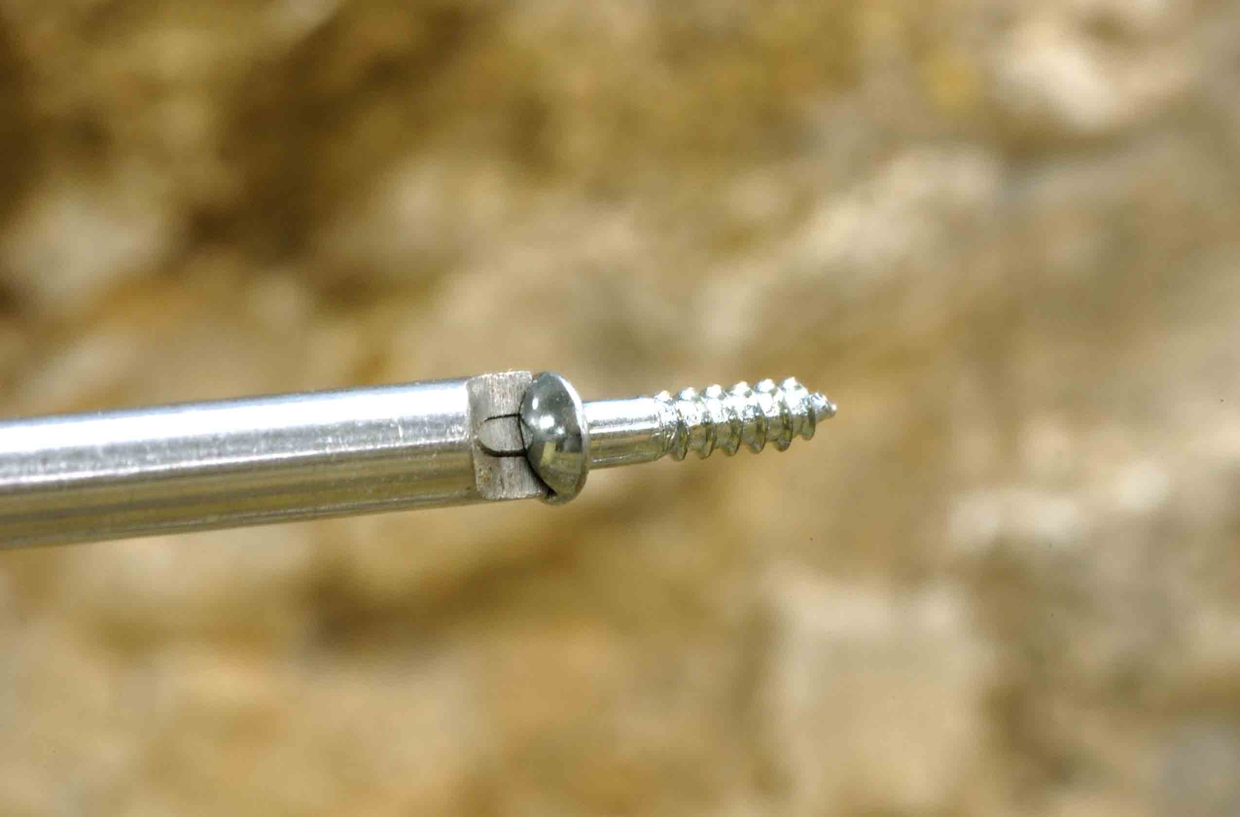 The holes were drilled with a Yankee drill driver and, thanks to a special screw holding screwdriver that I inherited from my father, the Tortoise machine was secured in place. The actuating wire was guided up through the hole in the throw bar while its other end was firmly locked in place on the movable arm of the Tortoise. The Dremel tool and cutoff disk were used to remove the excess length of wire, making sure it ends up being low enough to clear rolling stock, yet be long enough to stay in the throw bar. |
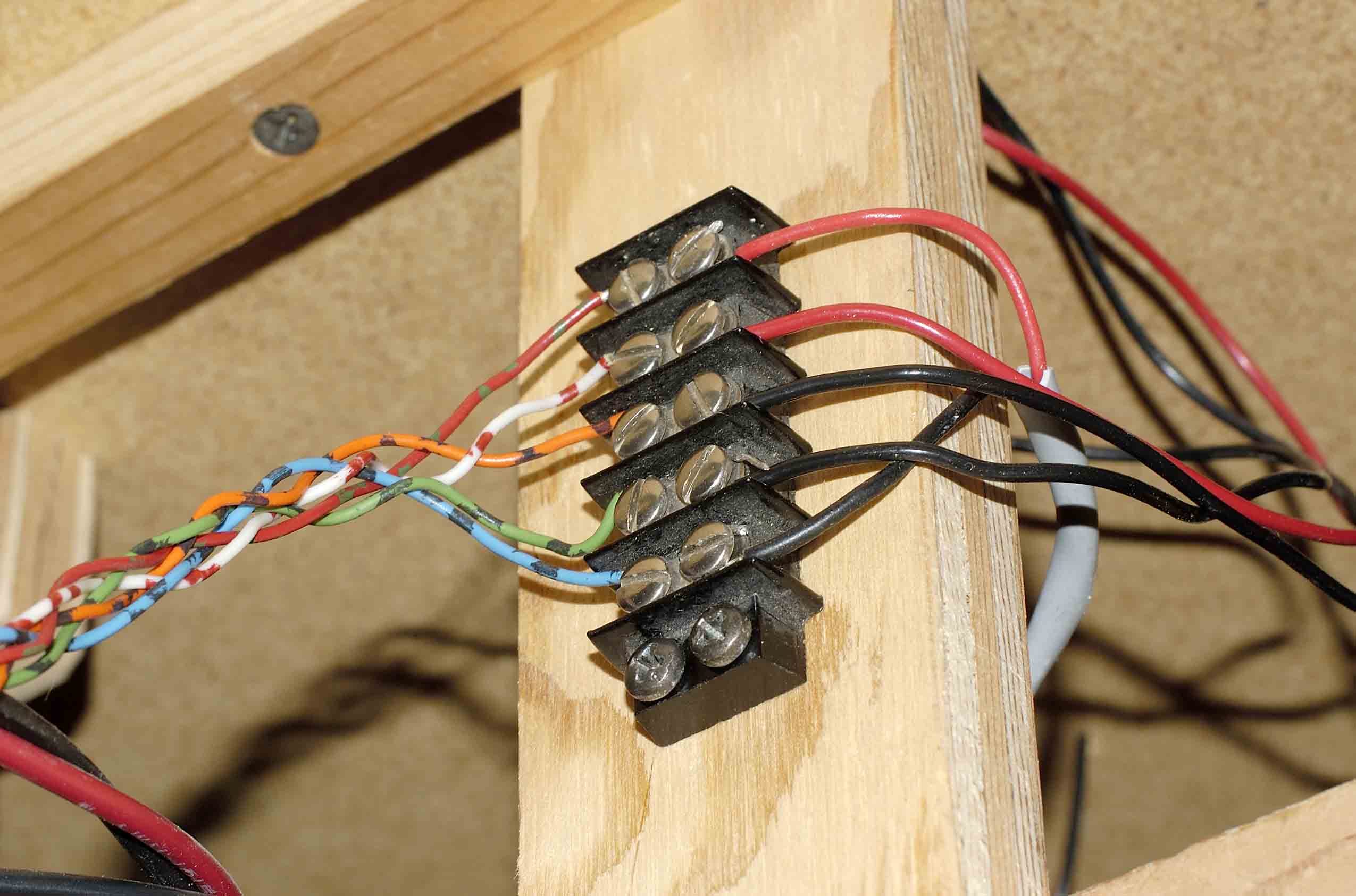 Prior to installing the Tortoise, light-weight, multi-colored, stranded wire attached to the appropriate soldering lugs. Some of the Tortoise machines are connected with quick, slip-on disconnects, but I didn't have any more so this one was simply, "hard wired." I only needed five wires for the connections and ran them to a terminal strip that I bought at a surplus electronics supply store. Three wires were connected to one set of the DPDT contacts within the Tortoise and two wires were connected their respective terminals in one of my control panels. It's a maze of wires behind these panels, but I had made provisions ten years ago for this turnout and I was happy to finally use them. I have wired the power feeds to the Tortoise machines to illuminate either a red or green LED, depending on which routing button is pressed on the panel. |  To finish the turnout, the throw bar was painted with a light gray acrylic craft paint, then stained with a dab of black shoe and rubbing alcohol solution. A high-target switch stand was installed along with a few shrubs, grasses, ballast and a sprinkle or two of ground foam completes the turnout. A light cleaning of the rail heads and it will be ready for use. |
| I know this was a long and drawn-out description of completing a turnout, but I thought I'd give the rotating pin method a try. As I mentioned earlier, prior to using either the machine screws, nuts or pins, I used to solder the point rails directly to the copper plating of the printed circuit board throw bars, but because of the back and forth movement the solder joints eventually weakened and broke. Since I've used the rotating connectors, everything has remained quite solid. I just wish I had discovered the brass pins earlier. | |