

Welcome to my world of Sn3 Scale Model Railroading

Building Loading Docks
By
Tom Troughton, MMR
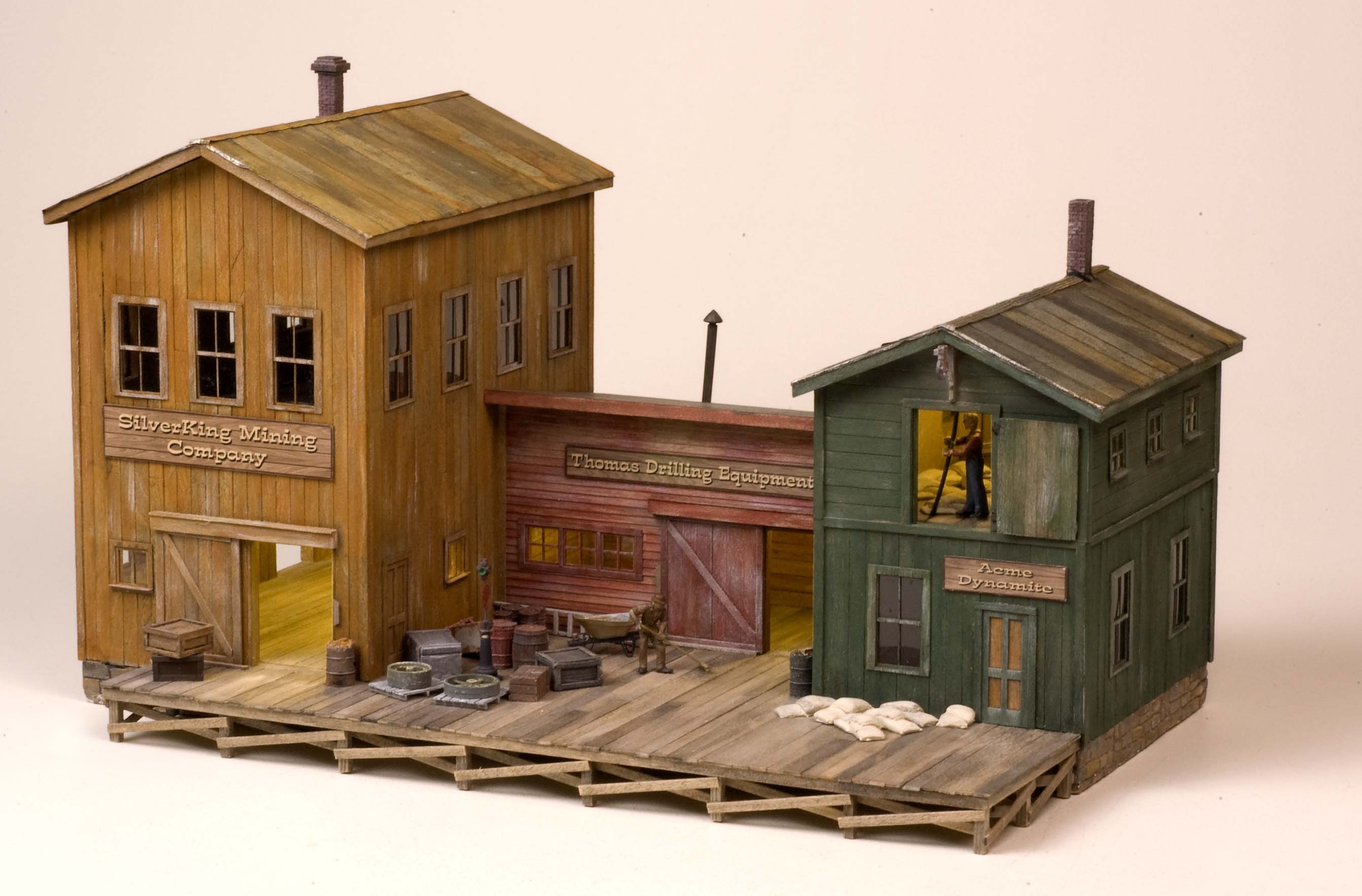 When I returned to model railroading in the late 1960's, I purchased a few HO scale "Fine Scale Miniatures" craftsman quality wood kits that included extremely detailed loading docks and platforms. When it came to building those components I followed the instructions and constructed them as described with their prototypical elements using stripwood supporting beams, square posts and diagonal bracing. After changing to Sn3 in 1995, I realized that there had to be a better, easier and faster way to build loading docks. The technique I used is described here and I believe the end result has the same appearance as one built using the board-by-board method. | ||
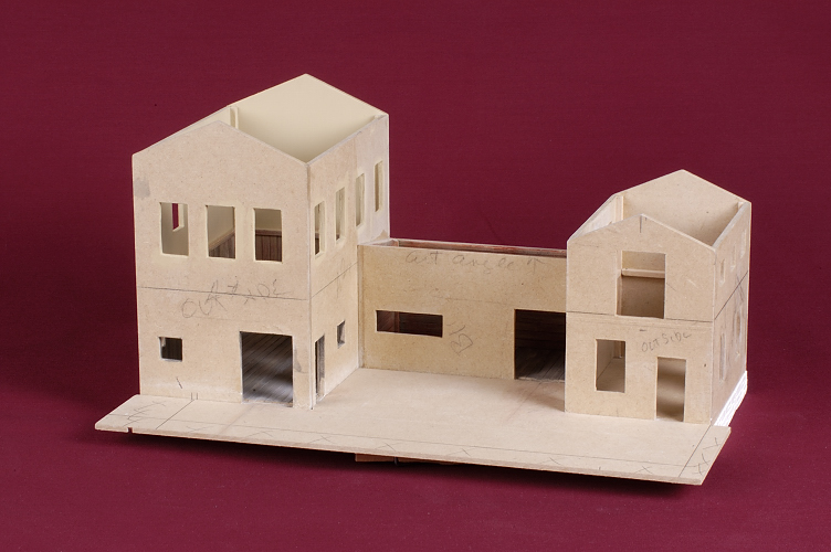 Photo 1. The process starts with a platform made from 1/8" thick untempered Masonite. I don't believe it's available any longer, but I still have a supply of the material that I've accumulated over the years and have used it to construct interior supports for many of my buildings. In this photo, it has been test fitted and temporarily supported in place to see how it would look. | 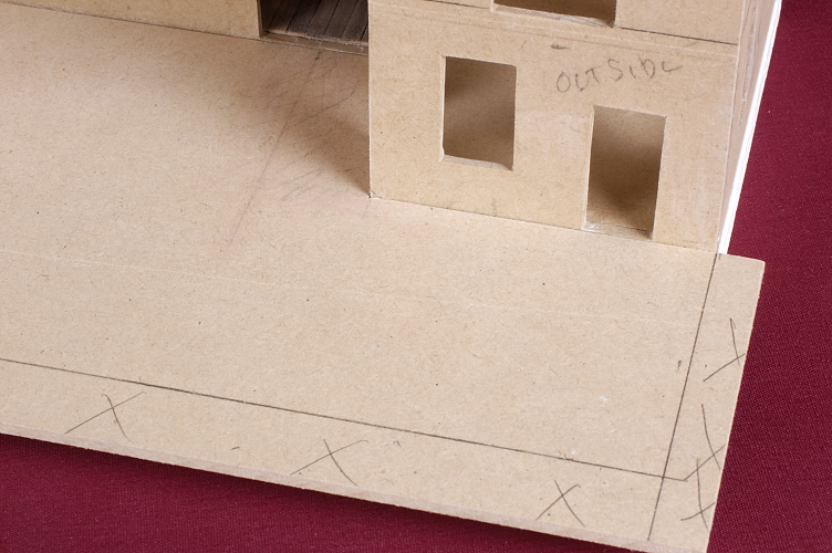 Photo 2. The solid pencil lines were marked on the platform surface so that they lined up with the exterior surface of the inner support structures of the three building components. They will serve as quides for the next step. | |
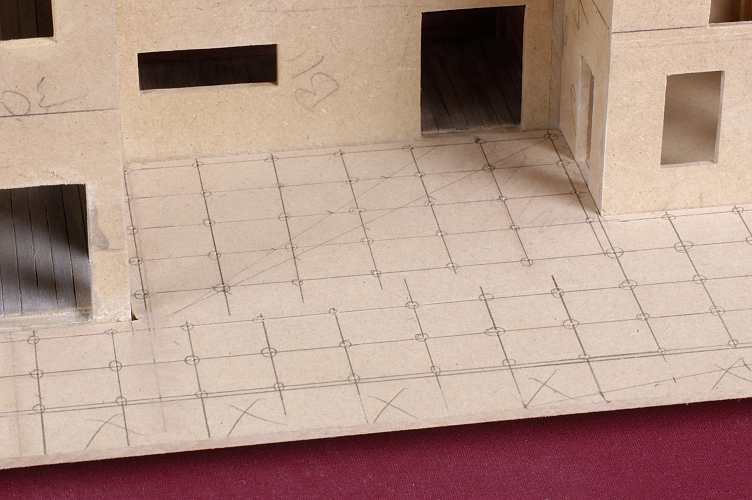 Photo 3. I initally marked off lines that were four scale feet apart. To determine the drilling location for holes that would hold the outer or edge support posts, I selected a drill that was slightly smaller than the scale 8"x8" posts that would be used to support the platform. The drilling locations were marked so that the edge of the drilled holes would be even with the outer perimiter pencil line drawn earlier. |  Photo 4. Once marked, the platform piece was taken to the shop and drilled. | |
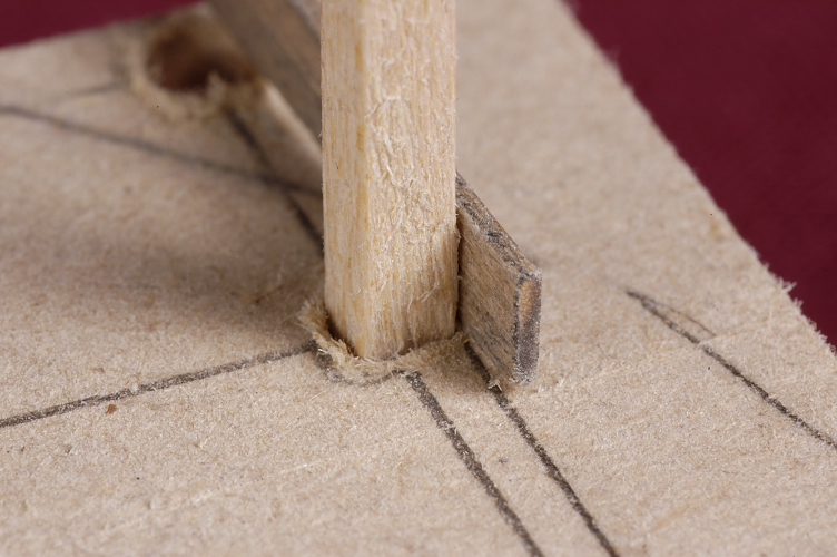 Photo 5. This photo shows why the drilling lines for the outer posts were placed where they were. When an 8" x 8" post was test fitted into the hole and a piece of the 2" x 10" stripwood band board was set in place, it lined up exactly on the outer permiter line. | 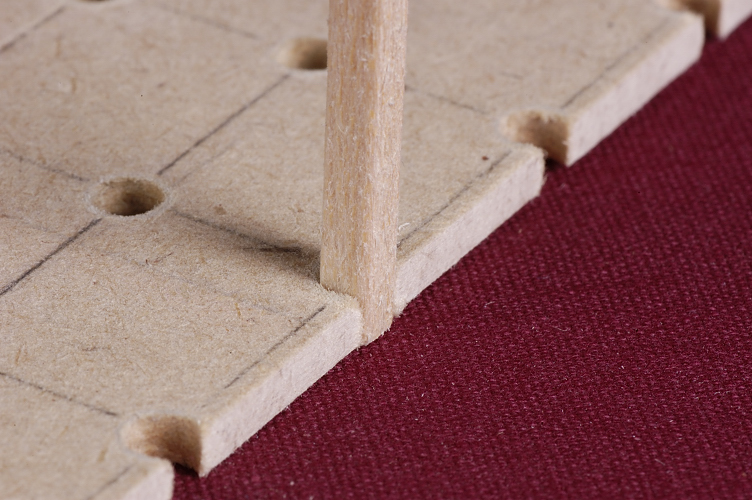 Photo 6. The Masonite panel was taken to the work shop and carefully sawn on the perimeter lines. A post was again test fitted into one of the holes and its outer edge lined up perfectly with the sawn line. | |
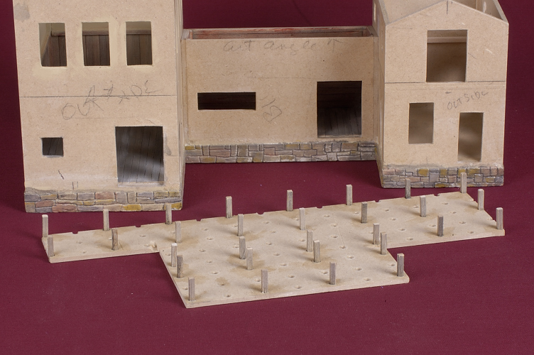 Photo 7. This photo shows the end result with the posts glued into place. In getting to this stage, it quickly became obvious that I had planned for too many supporting posts and decided to only use half of the drilled holes by skipping every other one while inserting the posts. They were initally secured in place with yellow carpenter's glue, but I also reinforced them with CA adhesive. | 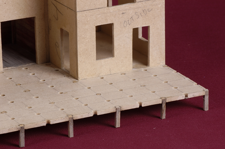 Photo 8. The Masonite panel was once again test fitted against the building to see how things would look. It's height was established so that the decking would be level with the floors of each of the three building units of the structure. | |
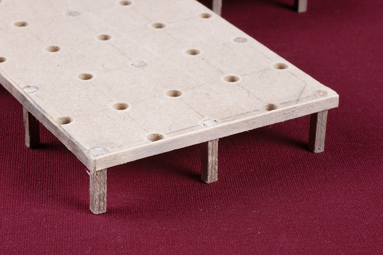 Photo 9. The 2" x 10" edging or band boards of the loading dock have been attached to the outer edge and flush with the surface of the Masonite. Because they are slightly wider than the thickness of the Masonite, they extend below it a small amount thereby hiding the solid underside. | 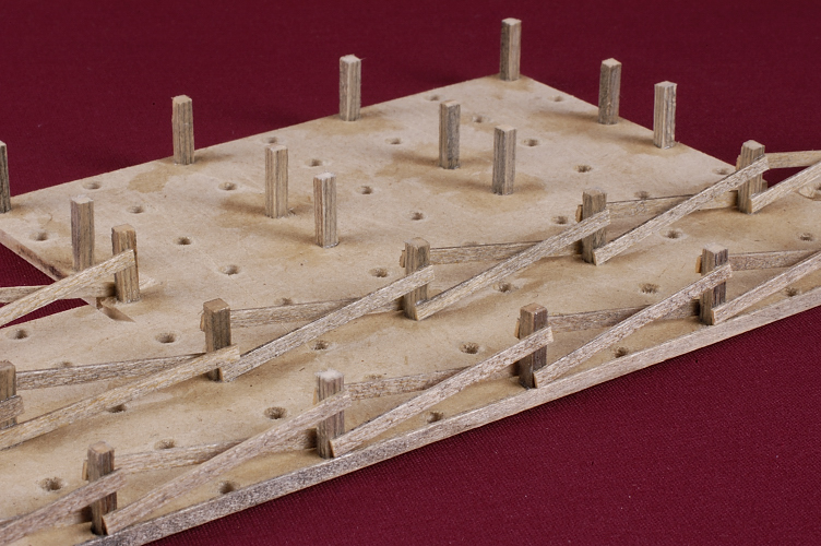 Photo 10. Since the loading dock component was still loose, it was a simple task to turn it over and attach the diagonal timbers to the support posts. Because the full underside of the dock would not be seen when the structure was placed on the layout, the rear rows of diagonal boards were not attached. | |
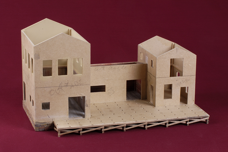 Photo 11. The dock component was set in place against the building to see how well it butted up against the side walls. | 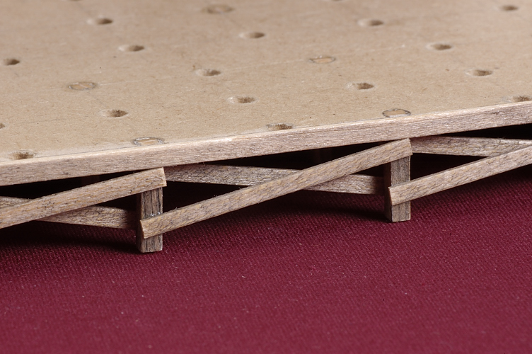 Photo 12. This is a view of the front, or track side, edge of the loading dock with the band boards and diagonal bracing in place. | |
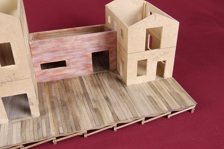 Photo 13. The pre-stained 2" x 12" decking has been attached, one board at a time, using Aleene’s Tacky Glue to hold them in place. After the glue had dried, the decking was given an additional application of the alcohol and black shoe dye stain to create a more weathered effect. | 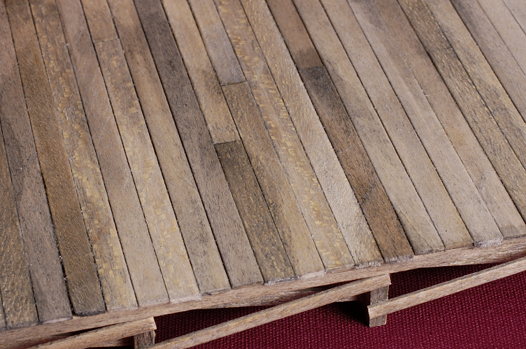 Photo 14. Colored pastel chalk powders were used to further enhance the weathering on the dock timbers. When the decking pieces were attached, their ends were allowed to extend slightly beyond the edging boards. | |
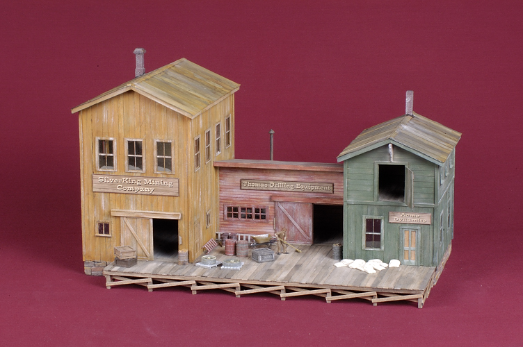 Photo 15. This is a posing bench view of the completed structure. It houses three companies associated with the Silver King Mining District on the layout. All the doors are movable and the roof pieces can be removed to gain access to the interiors for lighting and additional detailing. | 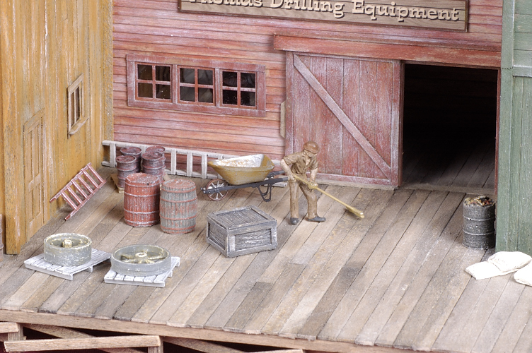 Photo 16. Pieces of extra detail parts as well as a dockman sweeping up loose debris add a bit of life to the dock. | |
 Photo 17. The decking looks great and there's no visible evidence that reveals how the actual loading dock was constructed. I didn't want to go through the process of creating all the prototypical timber framing when it was only going to be hidden when the flooring was placed on top of it. | 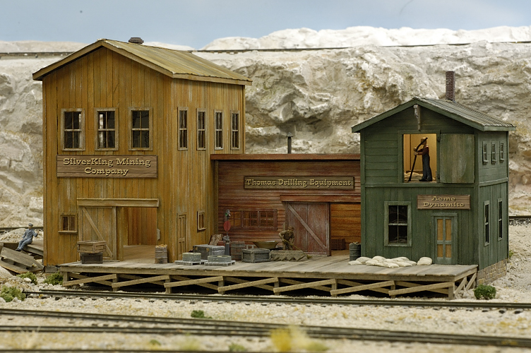 Photo 18. The mining company building with the busy loading dock is a major component of the small community of Silver King on my C&TT RR. It's a busy place when box cars of materials for the mines of the district are spotted at the dock for unloading. | |
Click Here To Return To Railroad Home Page